Ultra Low Carbon Bainitic Steels: Part Two
Abstract
Although one of the most hotly debated microstructure topics, control of bainitic transformation can lead to a range of diversified gains over the mechanical properties of the finished product.
Specific studies of the relationship between cooling rate and finished cooling temperature show interesting findings related to the distribution of granular bainite, martensite-austenite constituent, bainitic ferrite, and polygonal ferrite.
Microstructures of ultra-low carbon bainitic steels are often complex, consisting of mixtures of different ferrite morphologies, and therefore, wide combinations of mechanical properties can be achieved by controlling them. The bainitic transformation is one of the most complex and disputed phase transformations in steels and all microstructures found may not exhibit the typical bainitic type of transformation.
In the work of A.B.Cota and D.B.Santos on HSLA low-carbon bainitic steel containing B was submitted to torsion tests to simulate controlled rolling, followed by interrupted accelerated cooling. The final microstructure was found to contain complex mixture of granular bainite, small islands of martensite-austenite (MA) constituent, bainitic ferrite, and polygonal ferrite.
The combined effects of cooling rate and the finished cooling temperature on the microstructure are illustrated in Figures 1 (LM photomicrographs) and 2 (SEM photomicrographs). It can be seen from Figures 1(a) and 2(a) that the microstructure associated with the highest finish cooling temperature ( TFC = 650°C) exhibits a mixture of fine polygonal ferrite (with a volume fraction < 12%), granular bainite, and small islands of the MA constituent.
The MA constituent has a granular or equiaxed morphology (volume fraction < 4.5% and with islands of average size less than 2 mm). By contrast, the microstructures associated with the next lower finished cooling temperature (TFC= 500°C) [Figs. 1(b) and 2(b)] consist of granular bainite and bainitic ferrite. A small amount of polygonal ferrite is also in evidence in these microstructures.
In the case of the two higher finish cooling temperatures (TFC=650°C and TFC=600°C), the MA islands are distributed practically uniformly throughout the bainite matrix (Figure 3). This figure, a compilation of binary images in which the MA islands appear white, shows that the increase in cooling rate or decrease in finished cooling temperature implies a decrease in the volume fraction and the average size of the MA islands.
Figures 1(c)–(d) and 2(c)–(d) show that, for the lowest finish cooling temperature, TFC = 400°C, the microstructure is essentially bainitic, with fine laths of bainitic ferrite and interlath MA constituent.
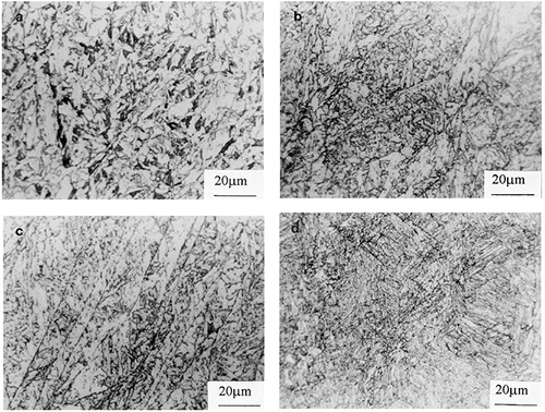
Figure 1: Light photomicrographs of samples cooled at different rates and with different finish cooling temperatures: (a) 6.3°C/s, 650°C; (b) 13.3°C/s, 500°C; (c) 6.3°C/s, 400°C; (d) 33°C/s, 400°C.
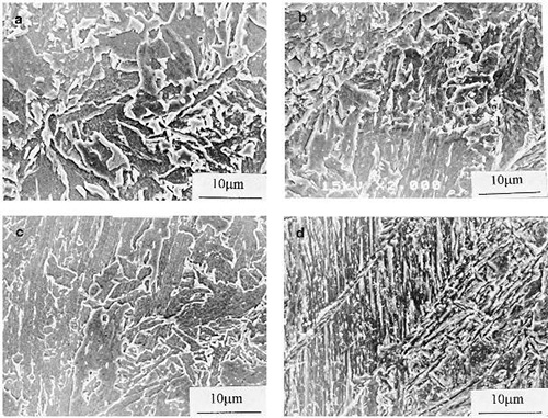
Figure 2: SEM photomicrographs of samples cooled at different rates and with different finish cooling temperatures: (a) 6.3°C/s, 650°C; (b) 13.3°C/s, 500°C; (c) 6.3°C/s, 400°C; (d) 33°C/s, 400°C.
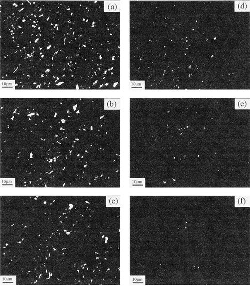
Figure 3: Binary images of samples cooled at different rates and with different finish cooling temperatures: (a) 6.38C/s, 650°C; (b) 13.0°C/s, 650°C; (c) 33°C/s, 650°C; (d) 6.3°C/s, 500°C; (e) 13.3°C/s, 500°C; (f) 33°C/s, 500°C. LePera’setchant; MA constituent is white.
Find Instantly Thousands of Metallography Diagrams!
Total Materia Horizon contains a unique collection of metallography images across a large range of metallic alloys, countries, standards and heat treatments.
Get a FREE test account at Total Materia Horizon and join a community of over 500,000 users from more than 120 countries.