Fatigue of Metals: Part Three
Abstract
This comprehensive article explores advanced concepts in metal fatigue, focusing on statistical analysis, cyclic stress-strain relationships, and low-cycle fatigue behavior. The discussion encompasses critical aspects of fatigue testing, stress-life relationships, and endurance limits across various metal types. Special attention is given to practical applications in nuclear pressure vessels, steam turbines, and power machinery design, with detailed analysis of fatigue properties in stainless steels and their industrial implications.
Understanding Stress-Life Relationships in Metal Fatigue
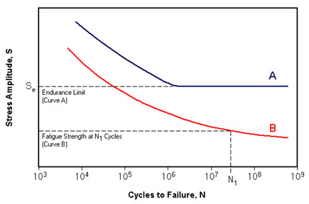
Fatigue strength determination involves applying varying levels of cyclic stress to test specimens until failure occurs. Modern laboratory testing employs multiple methods, including rotating bend, cantilever bend, axial push-pull, and torsion testing. Engineers typically present this data through stress-number of cycles to failure (S-N) curves, plotted on logarithmic scales. Due to the statistical nature of fatigue failure, multiple specimens undergo testing at each stress level to ensure reliable results.

Figure 1: Typical S-N curves with both continuous and limiting behavior
Endurance Limits and Material Behavior
Materials exhibit two distinct patterns in fatigue behavior. Some materials, particularly low-carbon steels, demonstrate a fatigue limit - a stress level below which failure theoretically never occurs. This limit typically approximates 40% of the material's tensile strength. However, most materials show a continuously declining stress-life curve, necessitating the specification of an endurance limit for a predetermined number of cycles.
Fatigue Strength Characteristics in Stainless Steels
Test Sensitivity and Variability
Fatigue strength measurements exhibit significant sensitivity to both testing methodology and specimen surface finish. Results frequently display scatter patterns, reflecting the complex nature of fatigue failure mechanisms in metals. This variability necessitates careful consideration in experimental design and data interpretation.
Research Findings on Fatigue Limits
Recent research provides valuable insights into stainless steel fatigue behavior. According to Avesta researchers, austenitic and duplex stainless steels typically demonstrate fatigue limits in air approximating their 0.2% proof strength levels. Their studies also revealed an important correlation between fatigue strength and stress fluctuation frequency, with higher frequencies generally resulting in decreased fatigue strength values.
Alternative research by Alan Haynes (NiDI) presents a more conservative assessment, suggesting that duplex stainless steels exhibit fatigue limits at approximately 50% of their ultimate tensile strength (Rm/UTS). This finding is further supported by INCO data (NiDI publication No. 2978), which provides comprehensive endurance limit data from reverse bending fatigue tests.
Table 1. Endurance Limit Data for Common AISI Stainless Steels
| AISI Type | Endurance Limit, MPa |
| 301 | 240 |
| 303 | 240 |
| 304 | 240 |
| 310 | 215 |
| 316 | 270 |
| 321 | 260 |
| 347 | 270 |
This table presents endurance limits for various AISI stainless steel grades, with values converted to MPa and rounded to the nearest 5 MPa.
Relationship Between Fatigue Strength and Material Properties
The fatigue strength, characterized by the fatigue limit So (stress amplitude) in Wöhler curves at 106 – 107 load cycles, demonstrates a clear relationship with tensile strength (Rm).
Table 2. Fatigue properties of stainless steel
| Steel type | So/Rm | Uncertainty | Limitations | |
| Stress ratio | R=-1 | R=0 | ||
| Austenitic 1.4301, 1.4310 (304, 301) | 0.45 | 0.35 | 0.04 | < Rp0.2 |
| Austenitic 1.4362, 1.4462 (2304, 2205) | 0.60 | 0.35 | 0.04 | < Rp0.2 |
This table illustrates the relationship between fatigue strength and material properties for different steel types, including stress ratios and their associated limitations.
Analysis of Fatigue Ratios
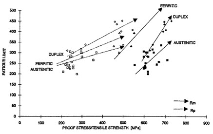
The relationship between fatigue limit (So) and yield strength (Rp) reveals interesting patterns across different steel types. While the So/Rp ratio shows considerable variation with strength, the So/Rm ratio remains relatively constant within each steel category. Notably, austenitic steels exhibit lower fatigue ratios compared to duplex varieties, primarily due to their lower yield-to-tensile strength ratio. The stress ratio (R = Smin/Smax) follows expected patterns, with fatigue limits decreasing as mean load increases.

Figure 2. The fatigue limit related to yield and tensile strength
This figure illustrates the relationship between fatigue limits and both yield and tensile strength across different steel types.
Practical Applications and Design Considerations
Engineers must consider that endurance limits aren't absolute values, but statistical measures derived from multiple tests. Surface finish, testing methodology, and environmental conditions significantly influence fatigue behavior. For design purposes, particularly in critical applications like nuclear vessels and turbines, these variations require careful consideration and appropriate safety factors.
Access Cyclic Properties of Thousands of Materials Now!
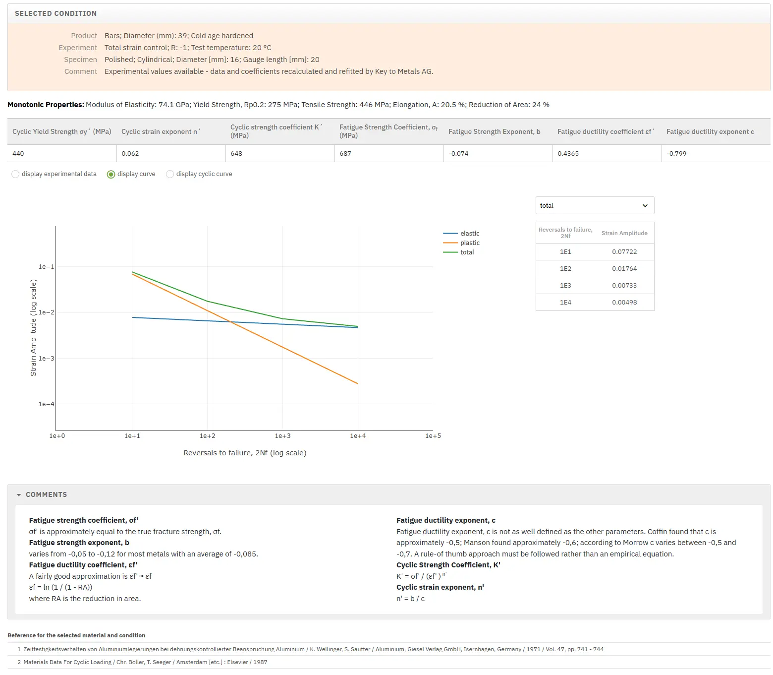
Total Materia Horizon includes a unique collection of fatigue properties of metallic and nonmetallic materials, for both low- and high cycle fatigue.

Get a FREE test account at Total Materia Horizon and join a community of over 500,000 users from more than 120 countries.