Fatigue of Metals: Part Two
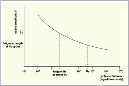
The basic method of presenting engineering fatigue data is by means of the S-N curve, a plot of stress S against the number of cycles to failure N. The most important concept is the S-N diagram, in which a constant cyclic stress amplitude S is applied to a specimen and the number of loading cycles N until the specimen fails is determined. Millions of cycles might be required to cause failure at lower loading levels, so the abscissa in usually plotted logarithmically.
Well before a microstructural understanding of fatigue processes was developed, engineers had developed empirical means of quantifying the fatigue process and designing against it. Perhaps the most important concept is the S-N diagram, such as those shown in Figure 1, in which a constant cyclic stress amplitude S is applied to a specimen and the number of loading cycles N until the specimen fails is determined. Millions of cycles might be required to cause failure at lower loading levels, so the abscissa in usually plotted logarithmically.

Figure 1: Typical S-N Curves
High-cycle fatigue, associated with low loads and long life (>103 cycles), is commonly analyzed with a "stress-life" method (the S-N curve), which predicts the number of cycles sustained before failure, or with a "total-life" method (endurance limit), which puts a cap stress that allows the material to have infinite life (>106 cycles).
Low-cycle fatigue, associated with higher loads (plastic deformation occurs) and shorter life (<103 cycles), is commonly used methods called "strain-life" to analyze or predict the fatigue life.
Fatigue cracking is one of the primary damage mechanisms of structural components. Fatigue cracking results from cyclic stresses that are below the ultimate tensile stress, or even the yield stress of the material. The name “fatigue” is based on the concept that a material becomes “tired” and fails at a stress level below the nominal strength of the material. The facts that the original bulk design strengths are not exceeded and the only warning sign of an impending fracture is an often hard to see crack, makes fatigue damage especially dangerous.
Factors Affecting Fatigue Life
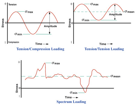
In order for fatigue cracks to initiate, three basic factors are necessary. First, the loading pattern must contain minimum and maximum peak values with large enough variation or fluctuation. The peak values may be in tension or compression and may change over time but the reverse loading cycle must be sufficiently great for fatigue crack initiation.
Secondly, the peak stress levels must be of sufficiently high value. If the peak stresses are too low, no crack initiation will occur. Thirdly, the material must experience a sufficiently large number of cycles of the applied stress. The number of cycles required to initiate and grow a crack is largely dependent on the first two factors.
In addition to these three basic factors, there are a host of other variables, such as stress concentration, corrosion, temperature, overload, metallurgical structure, and residual stresses which can affect the propensity for fatigue. Since fatigue cracks generally initiate at a surface, the surface condition of the component being loaded will have an effect on its fatigue life. Surface roughness is important because it is directly related to the level and number of stress concentrations on the surface.
The higher the stress concentration the more likely a crack is to nucleate. Smooth surfaces increase the time to nucleation. Notches, scratches, and other stress risers decrease fatigue life. Surface residual stress will also have a significant effect on fatigue life. Compressive residual stresses from machining, cold working, heat treating will oppose a tensile load and thus lower the amplitude of cyclic loading.
Figure 2 shows typical fatigue stress cycles under various loading conditions.

Figure 2: Typical fatigue stress cycles