Critical Crack Tip Opening Displacement (CTOD) Testing: Part One
Abstract
Crack tip opening displacement (CTOD) represents a crucial fracture mechanics parameter that bridges the gap between linear elastic and elastic-plastic fracture behaviors. As the only standardized test covering all fracture behaviors between stress intensity factor K and J-integral test extremes, CTOD provides engineers with a comprehensive tool for evaluating material toughness. This parameter enables determination of crack driving force in the crack tip vicinity by establishing relationships with component loading. The CTOD concept, introduced by Wells in 1963, serves as an essential engineering fracture parameter applicable across various structural materials that undergo extensive plastic deformation prior to fracture, making it indispensable for modern fracture toughness evaluation.
Understanding Fracture Mechanics Parameters
The evolution of fracture mechanics has produced three fundamental parameters that characterize material behavior under different conditions. The stress intensity factor K, proposed by Irwin in 1957, describes the intensity of elastic crack-tip fields and represents the foundation of linear elastic fracture mechanics. Subsequently, Rice introduced the J-integral in 1968 to characterize elastic-plastic crack-tip field intensity, establishing the basis for elastic-plastic fracture mechanics.
Between these two extremes lies the crack tip opening displacement (CTOD), conceptualized by Wells in 1963 as a practical engineering fracture parameter. This parameter uniquely serves as an equivalent alternative to both K and J factors in practical applications, making it exceptionally versatile for engineering assessments.
CTOD Testing Applications and Significance
Many high-toughness structural materials undergo extensive plastic deformation before fracture occurs. Consequently, traditional linear elastic fracture mechanics concepts require extension to accommodate elastic-plastic behavior. The CTOD test addresses this need by providing reliable measurements when plastic deformation precedes failure, allowing crack tips to stretch and open during the testing process.
The CTOD functions as a local parameter within the crack tip vicinity, enabling engineers to determine crack driving force by analyzing the relationship between CTOD measurements and component loading. Wells originally defined this essential parameter, with subsequent refinement through HRR models that present CTOD as a material resistance parameter against crack growth.
Experimental Challenges and Measurement Techniques
Experimental determination of actual CTOD during testing presents significant challenges because critical values occur within the specimen's mid-thickness region. However, Kolednik demonstrated that post-testing stereometry and fracture reconstruction enable determination of critical CTODi values.
The CTOD5 technique, designated as δ5 and introduced by Schwalbe and colleagues, represents one of the most established methods for direct CTOD measurement. This technique eliminates the need for calibration functions while requiring only basic mechanical parameters including Young's modulus, yield strength, and Poisson's ratio. The δ5 measurement involves measuring deformation between two points positioned 5 mm apart, with the crack tip centered at the 2.5 mm midpoint.
Specimen Configuration and Standards
Standard CTOD specimens feature two basic configurations: square or rectangular cross-sections. These specimens must conform to specific dimensional requirements to ensure reliable test results. The standardized approach ensures consistency across different testing facilities and applications.
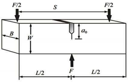
Figure 1: CTOD specimen configuration
Table 1. Dimensions of CTOD specimens
| Name | Symbol | Rectangular specimens | Square specimens | Deviation |
| Specimen thickness | B | B | B | ±0.5% B |
| Specimen width | W | 2B | B | ±0.5% W |
| Loading span | S | 4W | 4W | ±0.5% S |
| Specimen length | L | ≥4.5W | ≥4.5W | |
| Effective crack length* | a | 0.45W~0.55W | 0.45W~0.55W |
Note: For specimens of deposited metal test, the range of effective crack length may be 0.45W~0.70W.
All terminology and concepts related to fracture testing align with definitions established by ASTM E1823, which provides standard terminology for fracture toughness testing and evaluation. This standardization ensures consistent interpretation and application of CTOD testing results across the engineering community.
Uzyskaj dostęp do właściwości mechaniki pękania tysięcy materiałów już teraz!
Total Materia Horizon zawiera unikalną kolekcję właściwości mechaniki pękania, takich jak K1C, KC, wzrost pęknięć i parametry prawa Parisa, dla tysięcy stopów metali i obróbek cieplnych.
Uzyskaj BEZPŁATNE konto testowe w Total Materia Horizon i dołącz do społeczności ponad 500 000 użytkowników z ponad 120 krajów.