Strain Ageing of Steel: Part Two
Abstract
This article investigates strain ageing effects in two dual-phase steels: a carbon steel with 40% martensite and a microalloyed steel with 20% martensite. Specimens were pre-strained at 2%, 4%, and 6% levels, then aged at temperatures ranging from 25°C to 250°C for 30 minutes. Results demonstrate that both steels exhibit significant strain ageing, evidenced by changes in yield strength, ultimate tensile strength, and stress-strain behavior. While increased pre-strain enhanced ultimate tensile strength changes, it had a negative effect on yield point changes. The microalloyed steel showed slower ageing due to its complex chemistry containing nitrogen and carbide-forming elements, providing insights for structural steel applications.
Introduction to Strain Ageing Phenomena in Structural Steels
Strain ageing has been demonstrated to negatively impact low carbon structural steels used in various industrial applications. Numerous studies have investigated the effects of different parameters on the strain ageing characteristics of these materials, seeking to understand and mitigate these effects.
In the research conducted by S. Gündüz, the ageing behavior of two distinct steel types was studied: a carbon steel containing approximately 40% martensite by volume and a microalloyed steel with 20% martensite. The variation of mechanical properties, particularly the increase in yield strength (YS), was thoroughly assessed through tensile testing. Specimens underwent pre-straining in tension by 2%, 4%, and 6%, followed by ageing at temperatures of 25, 100, 150, 200, and 250°C for 30 minutes, and finally restraining to evaluate property changes.
Material Composition and Experimental Design
The investigation utilized two steel types: a commercially produced carbon steel without additional alloying elements and a microalloyed steel with various microalloying additions. Table 1 presents the detailed chemical compositions of both materials. All specimens underwent an annealing treatment at 900°C for 30 minutes, followed by air cooling to ensure microstructural homogeneity before testing.
Table 1. Chemical composition of the investigated steels
| %C | %Si | %S | %P | %Mn | %V | %Ti | %Al | %Nb | |
| Microalloyed Steel | 0.11 | 0.10 | 0.010 | 0.020 | 1.20 | 0.10 | 0.05 | 0.020 | 0.070 |
| Carbon Steel | 0.22 | 0.40 | 0.020 | 0.025 | 1.40 | - | - | 0.015 | - |
Testing Methodology and Strain Ageing Measurement
As outlined in the experimental design, specimens were initially pre-strained in tension by 2%, 4%, or 6%. After pre-straining, they were unloaded and subjected to ageing at temperatures ranging from 25°C to 250°C for a consistent duration of 30 minutes. Following the ageing process, tensile tests were conducted at ambient temperature with a crosshead speed of 2 mm/min. To ensure statistical reliability, at least three specimens were tested for each ageing temperature condition, and average values were calculated.
The increase in flow stress resulting from restraining was designated as the strain ageing parameter (ΔY2), as illustrated in Figure 1. For samples pre-strained in tension, ΔY2 was calculated as the difference between the lower yield stress after ageing and the flow stress at the conclusion of the pre-straining stage.
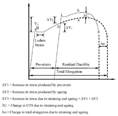
Figure 1: Stress–strain curve for low carbon steel strained to point A, unloaded, and then restrained immediately (curve a) and after ageing (curve b).
Stress-Strain Behavior Analysis
Figures 2 and 3 illustrate the stress-strain responses of both steel types under various pre-strain and ageing conditions. These diagrams provide visual representation of how mechanical behavior evolves with different treatment parameters.
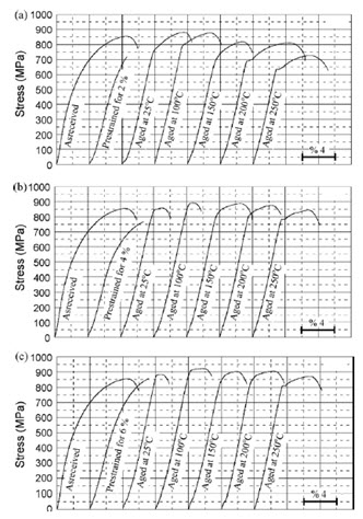
Figure 2: Variation of stress–strain curves of the dual phase carbon steel at different ageing temperatures for the pre-strains of 2% (a), 4% (b) and 6% (c).
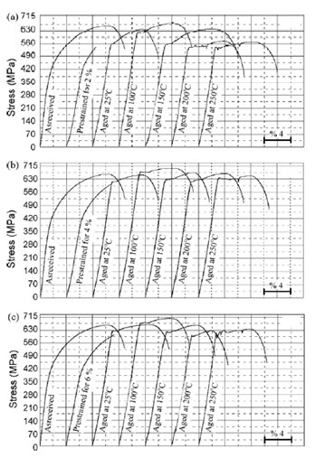
Figure 3: Variation of stress–strain curves of the dual phase microalloyed steels at different ageing temperatures for the pre-strains of 2% (a), 4% (b) and 6% (c).
Both the dual phase carbon steel and the microalloyed steel exhibited continuous yielding prior to any ageing treatment. This characteristic behavior can be attributed to the presence of mobile dislocations that were introduced during cooling from the intercritical annealing temperature. These dislocations facilitate the activation of multiple dislocation sources at relatively low strain levels, initiating simultaneous plastic flow throughout the specimen. This mechanism effectively suppresses discontinuous yielding that would otherwise be observed.
Effects of Pre-Strain and Ageing Temperature on Mechanical Properties
The research findings revealed several important relationships between processing conditions and mechanical properties:
- Both steel types demonstrated significant changes in stress-strain curve appearance with increasing ageing temperature across all pre-strain levels. This observation confirms that static strain ageing occurs in both the dual phase carbon steel and the microalloyed steel variants.
- Interestingly, while pre-strain had a negative effect on the change in yield strength (ΔY2) produced by subsequent ageing, increasing pre-strain markedly enhanced the change in ultimate tensile strength (UTS) for both steel types. This suggests that the ΔY2 parameter is less sensitive to dislocation density and primarily dependent on solute segregation per dislocation.
- Both steel varieties showed significant increases in yield strength, ultimate tensile strength, and ΔY2 values, while simultaneously experiencing decreased percentage elongation to fracture as the ageing temperature increased from 25°C to 100°C across all pre-strain conditions. This behavior can be attributed to atmosphere formation at dislocations and precipitation of carbonitrides during the strain ageing process.
- As ageing temperatures increased further to 150°C, 200°C, and 250°C, both materials exhibited a reduction in yield strength accompanied by increased percentage elongation. These changes indicate the onset of over-ageing, likely resulting from the tempering effect on martensite and coarsening of precipitates on dislocations.
Comparative Ageing Behavior Between Steel Types
A notable finding from this investigation was that ageing in the dual phase microalloyed steel proceeded at a slower rate compared to the dual phase carbon steel. This difference in ageing kinetics can be associated with the chemical composition of the microalloyed steel, which contains nitrogen and several carbide-forming elements including titanium, vanadium, and aluminum, in addition to carbon atoms. These elements influence dislocation mobility and solute interaction dynamics, resulting in the observed differences in ageing behavior.
Access Thousands of Stress-Strain Diagrams Now!
Total Materia Horizon includes a unique collection of stress-strain curves of metallic and nonmetallic materials. Both true and engineering stress curves are given, for various strain rates, heat treatments and working temperatures where applicable.
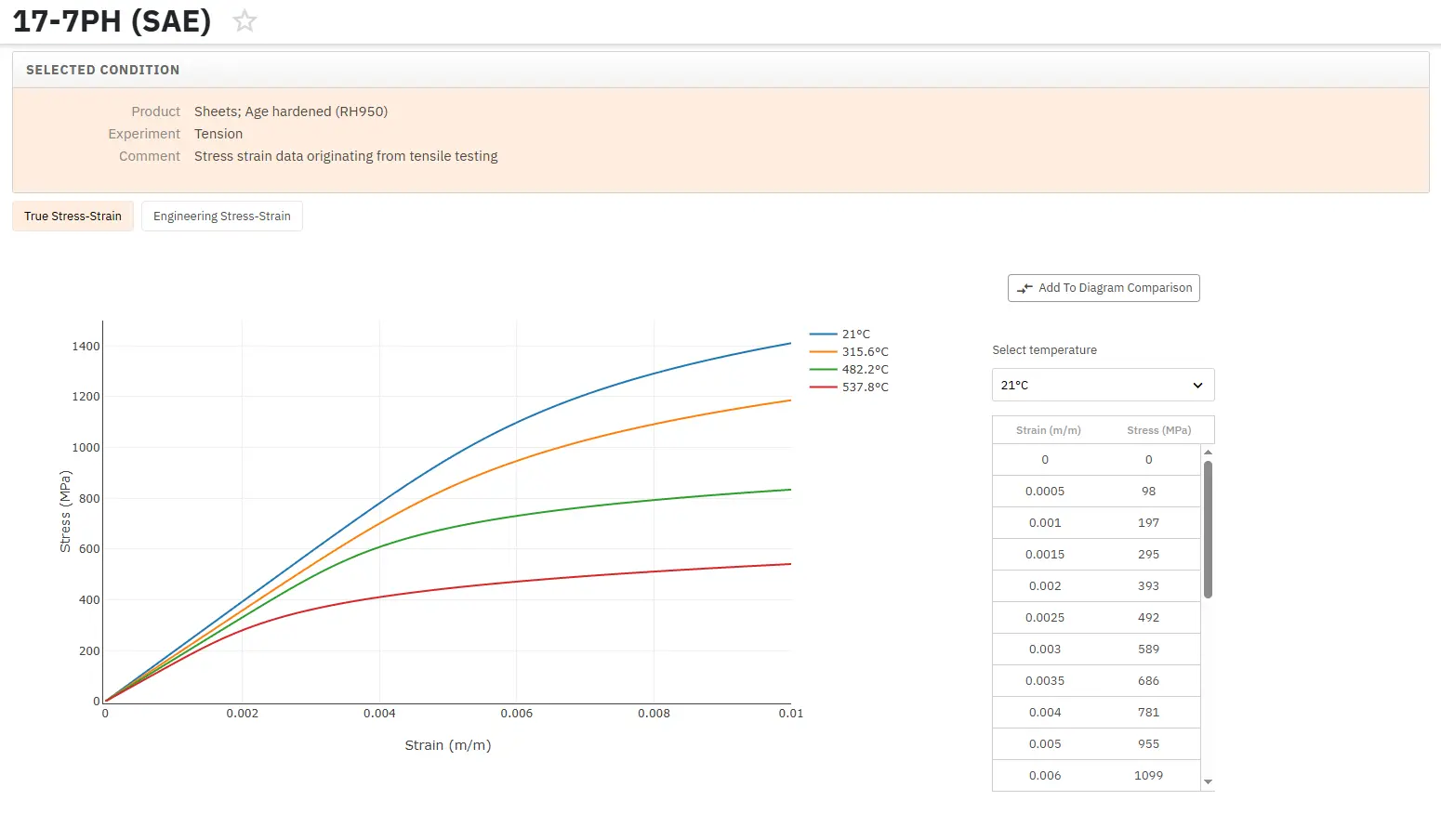
Get a FREE test account at Total Materia Horizon and join a community of over 500,000 users from more than 120 countries.