Twist Extrusion of Aluminum Alloys: Part Two
Abstract
Twist extrusion is a common forming method that belongs to a group of techniques known as severe plastic deformation (SPD) which are designed to generate ultrafine-grained microstructure without any changes in material geometry.
This paper will cover the results of a number of analyses such as the Von Mises stress distribution across the radial distance from the center of the cross-section.
Recently, severe plastic deformation processes are used to produce nano and ultrafine grained materials in bulk materials. Many researches aimed to increase the mechanical properties and special attention is needed to develop the innovative idea of the severe plastic deformation technique. The aim of the C. Sakthivel, and V. S. Senthil Kumar paper is to study the twist extrusion forming process of severe plastic deformation of AA 7075 Aluminium alloy. In this study, the hardness of the sample was analyzed at room temperature after high temperature annealed condition.
It is seen that the hardness value is increased in the right corner of the specimen due to its rotational direction of the twist channel effect, and the effect of grain refinement that occurred in the sample. The micro hardness varies more from the center towards the corner region of the sample. The microstructure of the constituent phases has changed very little along the direction of the twist extrusion. To investigate the extent of the zones of plastic flow in the specimen, the specimens were sectioned and analyzed at intervals of 10 mm starting from the twisting zone.
It is evident from Figure 1 that the hardness increases significantly at the end indicating that one pass TE has been completed. There is a consequent increase in the hardness of the AA 7075 one TE pass sample. This hardness variation occurred due to refinement of the grains which is evident from Figure 1.The initial hardness of as annealed specimen is 88 HV. By performing one pass TE the hardness of about 136 HV was developed. However, by employing TE processes with twist channel entry to exit, the hardness value increases from 88 HV to 136 HV.
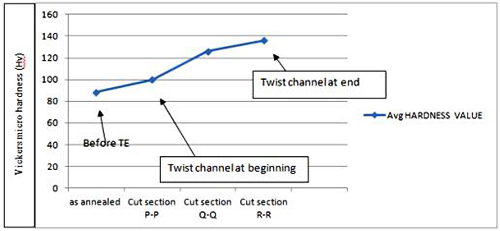
Figure 1: Average Vickers micro hardness values before TE and during TE. Cut Section of the extruded sample: P-P: cut section of the sample at 10mm from the twist channel entry; Q-Q: cut section of the sample at 20 mm from the twist channel entry; R-R: cut section of the sample at 30 mm from the twist channel entry.
In the study of S. S. Hosseini Faregh and A. Hassani, the twist extrusion process is modeled by ABAQUS finite element software. Three different approaches are used for prediction of strain field distribution for higher passes of TE. The finite element FE results are compared with the experimental results of twist extruded AA6063 aluminum alloy specimens. A sensitivity analysis has been implemented to choose the proper element size and friction coefficient during simulation. The microstructures of TE samples have been observed by SEM microscopy and analyzed by Pixcaviator software. Comparing the results of the microstructure study and FE shows that importing the material properties and deformation field from the previous pass to the current pass is the best way to simulate a multi-pass twist extrusion process. The plastic strain distributions show that the effective plastic strain is higher at the corner of the samples than at the center of it. The FE results show that the maximum Von-Mises stress increases at the corner elements by increasing the extrusion passes from 42 MPa at pass #1 to 110 MPa at pass #7. Most of this increase occurs in the first three passes.
Figure 2 shows the Von Mises stress distribution across the radial distance from the center of the cross-section of the sample for passes #1, #2, #3 and #7.
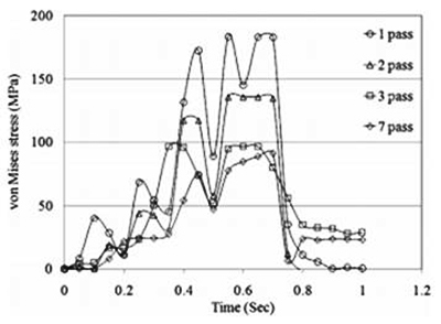
Figure 2: Variation of the Von Mises stress distribution across the radial distance from the center of the cross-section of the sample for passes #1, #2, #3 and #7.
Figure 3 shows the variations of the Von Mises stress during the deformation time for passes #1, #2, #3 and #7 of the TE process. Figure 4 shows the variation of plastic strain for the same passes. The stress increased at the beginning of the process. After passing the sample from the twist channel, the stress decreased. The peripheral regions of the sample were subjected to considerable shear stresses due to the friction of the die and surface of the sample.
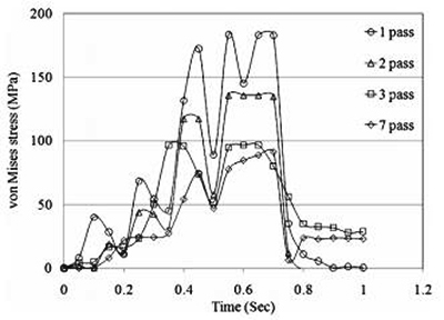
Figure 3: Variations of the Von Mises stress during the deformation time for passes #1, #2, #3 and #7.
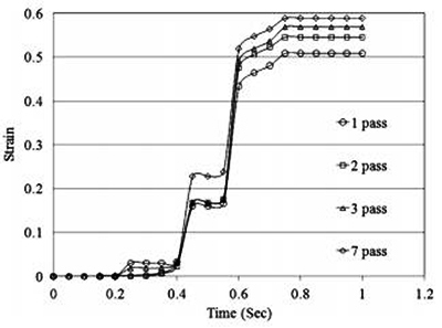
Figure 4: Variation of plastic strain during deformation for passes #1, #2, #3 and #7.
Figure 5 shows the variation of plastic strain during deformation for the center and corner elements in the twist extruded sample. The plastic strains obtained from the experimental results are shown in Figure 6. Comparing the results of finite element modeling and the results obtained from the image analyses of the TE samples indicates that the expanded finite element model can predict induced strains very well (5% difference). The grain refinement size and dependent properties can be predicted with acceptable error by determining the induced strains from the finite element results.
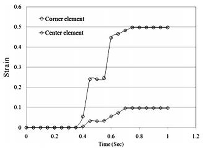
Figure 5: Plastic strain variation at center and corner in pass #1 TE.
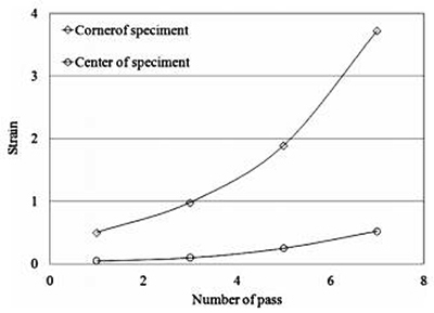
Figure 6: Variation of plastic strain in multi-pass TE calculated from image analysis.
Access Precise Properties of Aluminum Alloys Now!
Total Materia Horizon contains property information for 30,000+ alumiums: composition, mechanical, physical and electrical properties, nonlinear properties and much more.
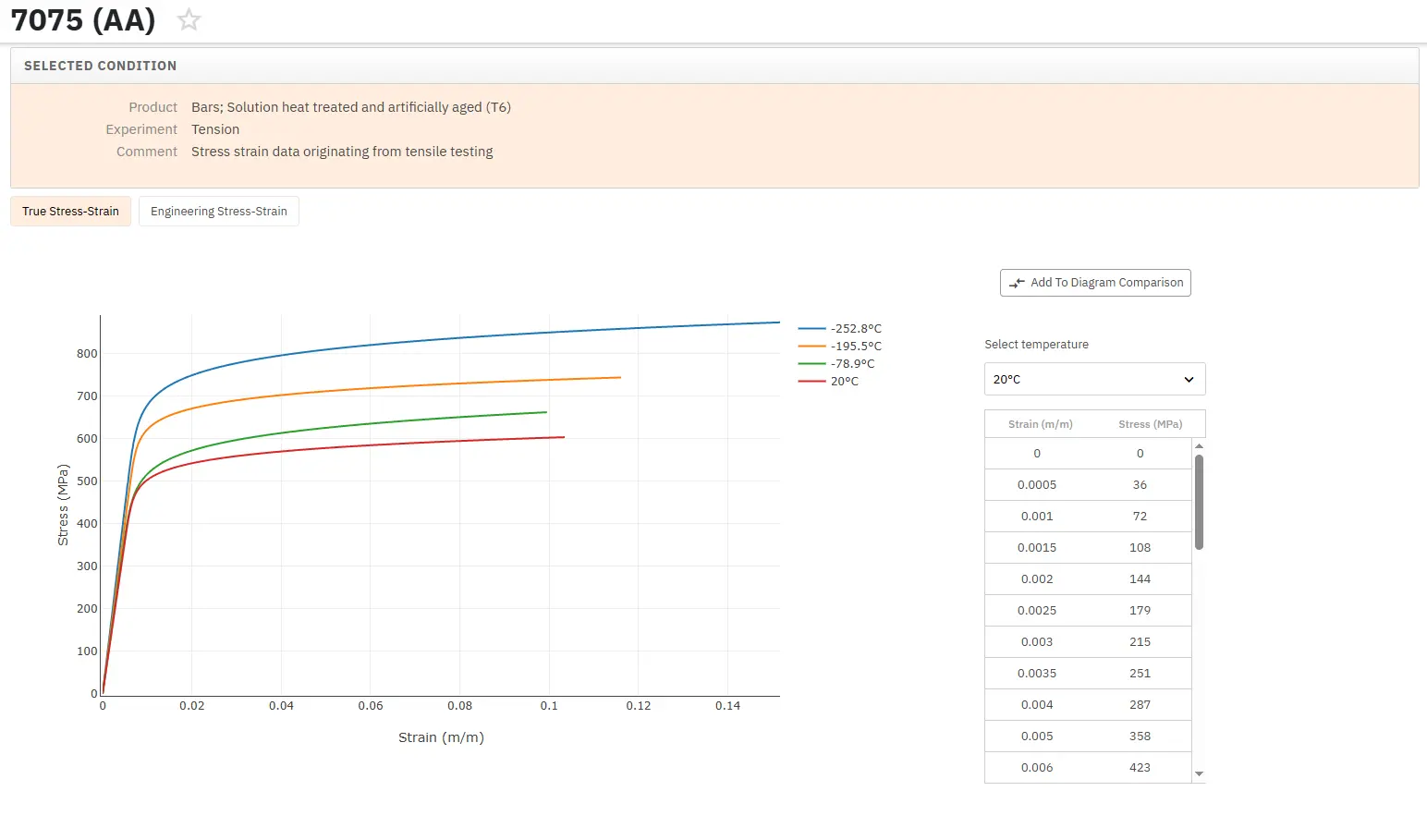
Get a FREE test account at Total Materia Horizon and join a community of over 500,000 users from more than 120 countries.