Eddy Current Testing
Abstract
The application of non-destructive test methods in quality control of semi-finished and finished products is of maximum economic importance in modern industry. The development of the eddy-current method of inspection has involved the use of several scientific and technological advances, including electromagnetic induction, application of induction coils, improved instrumentation resulting from developments of vacuum tubes and semiconductors, and improved signal display and recording.
The application of non-destructive test methods in quality control of semi-finished and finished products is of maximum economic importance in modern industry.
The development of the eddy-current method of inspection has involved the use of several scientific and technological advances, including the following:
- Electromagnetic induction
- Theory and application of induction coils
- The solution of boundary-value problems describing the dynamics of the electromagnetic fields within the vicinity of induction coils, and especially the dynamics of the electromagnetic fields, electric-current flow and skin effect in conductors in the vicinity of such coils
- Improved instrumentation resulting from developments of vacuum tubes and semiconductors, which led to better measurement techniques, and response to subtle changes in the flow of eddy currents in metals
- Metallurgy and metals fabrication
- Improved instrumentation, signal display and recording.
Since Dr Förster constructed his first equipment there has been a dramatic evolution within the field of eddy current testing. In particular the developments during the time period 1975-85 have been phenomenal, both with respect to equipment and with respect to applications of the method.
In the mid-1980s the first generation of microprocessor-based equipment began to appear on the market. It became possible to store calibrated data, reference and defect indications.
ASTM standards for eddy current testing include:
- Eddy Current Examination of Copper and Copper-Alloy Tubes
- Eddy Current Examination of Steel Tubular Products using Magnetic Saturation)
- Coating Thickness by Magnetic-Field or Eddy Current Test Methods
- Eddy Current Examination of Tubular Products
- Eddy Current Sorting of Ferrous Metals
- Eddy Current Examination of Nickel and Nickel Alloy Tubular Products
- Eddy Current Examination of Nonmagnetic Heat Exchanger Tubes
- Eddy Current Sorting of Nonferrous Metals
- Eddy Current Measurements of Electrical Conductivity
- Eddy Current Examination of Continuously Welded Ferromagnetic Pipe and Tubing above the Curie Temperature
- Eddy Current Examination of Ferromagnetic Bar above the Curie Temperature
Eddy-current Instruments
A wide range of different types of equipment are available depending upon the area of application. The equipment differs primarily with respect to physical design, for the principles of operation are identical for the various devices. There is also a tendency to produce equipment with a wide range of facilities which can be used for many different types of examination.
Defectometer
Defectometer is fitted with a 3-position frequency selector, so that only 2 standard probes are required to cover the entire range of ferromagnetic, non-ferromagnetic and austenitic metals. A separate lift-off compensation control is fitted so that cracks can still be accurately measured, even in the presence of thick oxide or paint films.
Its main field of application is that of aircraft maintenance. This field of application covers detection of e.g.:
- cracks on wing surfaces (in particular near to rivets)
- hair line cracks in the blades of the engine turbines
- fatigue cracks in rims or
- corrosion.
Other example of applications:
- the car and semi-finished products industries
- the metal-working industry
- the power -generation industry.
Defektomat
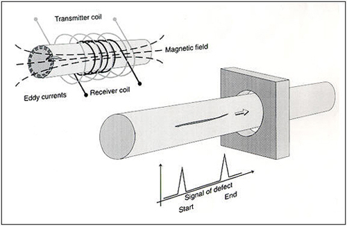
The eddy current process has been used successfully in the testing of wires, bars and pipes for many years.
All-round or segmented through-type coils or alternatively rotary probes are used, depending on the shape of the cross-section, the test speed, test temperature and the fault detection required.
In case of testing of rails, a combination of stationary rotary heads and edge coils is used.

ANDSCAN
ANDSCAN is a versatile portable inspection system designed for manual scanning of flat, curved or even irregular shaped components in the aerospace, nuclear, petrochemical and many other industries where precise, repeatable inspections are required. It is most commonly utilized with ultrasonic or eddy current inspections, although it could also be used in conjunction with mechanical impedance bond testing or other inspection instruments.
ANDSCAN provides accurate, repeatable fingerprinting for the integrity of composite, ferrous and non-ferrous materials. It is particularly suited to the examination of large flat or curved areas such as aircraft wings, pressure vessels and large critical component.
High resolution color graphics produce images of defects at the desired magnification, which can be stored for future analysis or later additional scanning. Eddy current scanning is ideal for use with an eddy current instrument, to detect either flaw, corrosion in aircraft panels or for material characterization in critical components.
WeldScan
WeldScan is an eddy current technique for detecting and sizing fatigue cracks in ferrous welds. WeldScan is also the trade name of a Hocking range of probes dedicated to this task.
WeldScan probes offer a cost-effective alternative to Magnetic Particle Inspection (MPI or MT) for in-service inspection of ferrous steel welds. They can detect surface breaking fatigue cracks through non-conducting surface coatings up to 2 mm and are therefore less expensive and quicker to use than any other technique when paint removal is required.
WeldScan incorporates a balanced sensor to minimize the effects of material variations and probe lift-off in the weld and heat affected zone. This design of probe greatly reduces the problems of inspecting uneven and undressed weld surfaces where there will also be changes in coating thickness.
Instrument for Crack Depth Measurement
For measuring the depth, length and angle of surface cracks up to 100 mm for all electrically conductive materials, the DC potential probe method can be used. This method comes into its own when it becomes difficult to evaluate angled or very short but deep cracks.
A DC current is applied to the test area on the test object which propagates (cushion shaped) vertically to the run of the crack. The potential difference at the crack position is a quantity for the crack depth.
If this potential difference (UR) is compared to the potential difference of a crack-free surface (U0), the quotient UR/U0 forms a quantity, independent of material, relative to the crack depth.
Find Instantly Precise Material Properties!
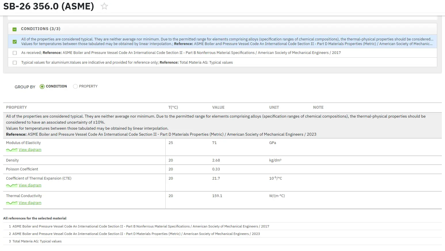
Total Materia Horizon contains physical, thermal and electrical properties for hundreds of thousands of materials, for different temperatures, and much more.

Get a FREE test account at Total Materia Horizon and join a community of over 500,000 users from more than 120 countries.