Charpy Impact Test for Metallic Materials
Abstract
The Charpy impact test is a standardized method for evaluating the impact strength of metallic materials, as specified by European Standard EN 10045. This test measures a material's ability to absorb energy during fracture by using a pendulum-based apparatus to strike a notched specimen. The test provides critical data about material toughness through the measurement of absorbed energy in joules. This comprehensive guide covers the test piece specifications, testing procedures, and machine requirements, including detailed information about specimen dimensions, notch types (U and V), and testing conditions. Understanding these parameters is essential for ensuring accurate and reliable impact strength measurements in metallic materials.
Introduction to Charpy Impact Testing
The Charpy impact test method, governed by European EN 10045 standard, provides essential information about a material's impact strength. This standardized approach ensures consistent and comparable results across different testing facilities. The test involves breaking a notched specimen with a single blow from a swinging pendulum under carefully controlled conditions.
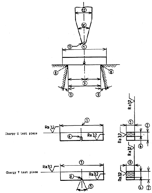
Table 1. Characteristics of test piece and testing machine
| Reference (Figure 1) | Designation | Unit |
| 1 | Length of test piece | mm |
| 2 | Height of test piece | mm |
| 3 | Width of test piece | mm |
| 4 | Height below notch | mm |
| 5 | Angle of notch | Degree |
| 6 | Radius of curvature of base of notch | mm |
| 7 | Distance between anvils | mm |
| 8 | Radius of anvils | mm |
| 9 | Angle of taper of each anvil | Degree |
| 10 | Angle of taper of striker | Degree |
| 11 | Radius of curvature of striker | mm |
| 12 | Width of striker | mm |
| - | Energy absorbed by breakage KU or KV | Joule |

Figure 1. Charpy impact test
Test Piece Specifications and Requirements
Standard Dimensions and Configuration The standard test piece must conform to precise specifications with a length of 55 mm and a square cross-section measuring 10 mm on each side. A notch must be positioned at the center of the specimen's length. The positioning and preparation of this notch are crucial for accurate test results.
Notch Types and Specifications
- V-Notch Configuration: The V-notch configuration requires a 45° angle with a 2 mm depth and a 0.25 mm radius at the base of the notch. In cases where standard test pieces cannot be obtained from the material, reduced sections with widths of 7.5 mm or 5 mm may be used, with the notch cut into one of the narrow faces.
- U-Notch (Keyhole) Configuration:The U-notch, also known as the keyhole notch, requires a 5 mm depth with a 1 mm radius at the base. Complete machining is required for all test pieces, except in the case of precision cast foundry pieces, where the faces parallel to the notch symmetry plane may remain unmachined.
Dimensional Tolerances
The standard specifies precise tolerances for test piece dimensions. Length tolerance is ±0.6 mm for both notch types. Height tolerances differ between configurations, with U-notch specimens allowing ±0.11 mm and V-notch specimens requiring a tighter ±0.06 mm tolerance. The angular tolerance for both the notch symmetry plane and adjacent longitudinal faces is set at ±2°.
Machining and Preparation Guidelines
Result comparison is only valid between test pieces of identical form and dimensions. The machining process must minimize material alteration, avoiding excessive cold working or heating. The notch preparation must ensure no visible parallel grooves at the base. Specimen marking should occur at least 5 mm from the notch and only on surfaces that won't contact the supports or anvils during testing.
Testing Machine Specifications and Operation
Machine Requirements
Testing machines must be rigidly constructed and installed in accordance with European Standard 10045 part 2. The standard nominal energy requirement is 300±10J for standard dimension test pieces.
Energy Absorption Designation
Results are designated using KU for U-notch specimens and KV for V-notch specimens. These basic designations are supplemented with additional information about machine energy capacity and specimen dimensions when applicable.
Testing Machine Energy Classifications
The standard allows for various machine energy capacities, which are indicated in the designation. For example, KV 150 indicates 150J available energy, while KU 100 indicates 100J available energy. A complete notation such as KU 100 = 65J indicates a nominal energy of 100J using a U-notch specimen with 65J absorbed during fracture.
Subsidiary V-Notch Test Specifications
For subsidiary V-notch tests, the notation includes both machine energy and specimen width. For instance, KV 300/7.5 indicates 300J energy capacity with a 7.5 mm specimen width. Similarly, KV 150/7.5 = 83J denotes a test using 150J nominal energy on a 7.5 mm wide specimen, resulting in 83J absorbed energy.
Testing Conditions
The test piece must be positioned against the anvils so that the notch symmetry plane lies within 0.5 mm of the anvil symmetry plane. Unless otherwise specified in the product standard, testing should occur at approximately 23°C.
Applicable Standards
The test methodology aligns with multiple national and international standards, including DIN 51306 (1983), NFA 03-508 (1985), BS 131 Part 4 (1972), and ISO 442 (1965).
Find Instantly Precise Material Properties!
Total Materia Horizon contains mechanical and physical properties for hundreds of thousands of materials, for different temperatures, conditions and heat treatments, and much more.

Get a FREE test account at Total Materia Horizon and join a community of over 500,000 users from more than 120 countries.