Testing Methods for JIS Steel Materials
Abstract
This article examines tensile testing methods for determining mechanical properties of steel materials according to Japanese Industrial Standards (JIS). It details the process of tensile testing, where specimens are subjected to increasing loads until fracture, allowing measurement of key properties such as elastic modulus, yield strength, and ductility. The article outlines various test piece classifications based on material form and dimensions, with specific focus on JIS standardized specimens. These testing methods provide comprehensive material characterization essential for quality control and material selection in industrial applications.
Introduction to Tensile Testing
The tensile test represents the most widely used method to determine the mechanical properties of materials. In this standardized procedure, a specimen is pulled until fracture occurs, while continuously measuring both the applied load and specimen elongation. From these measurements, stress and strain values are calculated and used to construct a stress-strain curve, which reveals critical material properties including elastic modulus and yield strength.
The highest load recorded during testing determines the tensile or ultimate strength of the material. After fracture, measurements of the final length and cross-sectional area allow calculation of percent elongation and percent reduction of area, providing valuable indicators of material ductility. By tracking instantaneous dimensions during testing, true stress and true plastic strain can be derived from load and elongation data.
Further analysis using a logarithmic plot of true stress versus true plastic strain reveals the strain hardening characteristics of the material. This comprehensive approach allows engineers to extract extensive information about mechanical properties from a single test.
International Testing Standards
Numerous organizations worldwide have developed standardized methods for conducting tensile tests. In the United States, ASTM standards are commonly referenced to define tensile test procedures and parameters. Internationally, other prominent standards organizations include:
- Japanese Industrial Standards (JIS)
- Deutsche Institut für Normung (DIN)
- International Organization for Standardization (ISO)
While other technical groups in the United States have developed additional standards, these generally derive from the foundation established by ASTM E.8.
Test Piece Configuration and Testing Equipment
Tensile test specimens are typically manufactured in either circular or flat configurations, with standard circular specimens having a diameter of 12.5mm.
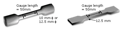
Figure 1: Typical test pieces showing various specimen configurations
The tensile test specimen is secured in the grips of a tensile testing machine. During testing, the grips separate at a constant rate while a load cell measures the applied force and an extensometer records specimen extension.
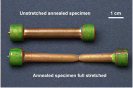
Figure 2: Unstretched and full stretched specimens
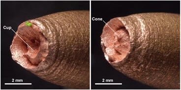
Figure 3: Test pieces after tensile testing
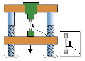
Figure 4: Tensile test machine
It's important to note that tensile testing is generally destructive, as specimens undergo permanent deformation and typically fracture during the procedure.
JIS Classification of Test Pieces
The Japanese Industrial Standard classifies test pieces into proportional and non-proportional categories depending on the form and size of the material. Table 1 provides a comprehensive classification system.
Table 1. Classification of test pieces by form including flat, bar, tubular, arc section, and wire specimens
| Form of test piece | Flat form test piece | Bar form test piece | Tubular form test piece | Arc section test piece | Wire form test piece |
| Proportional test piece | N°14B | N°2; N°14A | N°14C | N°14B | |
| Non-proportional test piece | N°1A; N°1B; N°5; N°13A; N°13B | N°4; N°10; N°8A; N°8B; N°8C; N°8D | N°11 | N°12A; N°12B; N°12C | N°9A; N°9B |
The selection of appropriate test piece type should follow the requirements specified in the standard for each particular material. Table 2 provides recommended test piece selections based on material type and dimensions.
Table 2. Detailed classification system correlating materials with appropriate test piece selections
| Material | Test Piece | Remarks | ||
| Form | Dimensions | Proportional | Non-proportional | |
| Sheet, Plate, Shape, Strip | *t > 40 | N°14A | N°4; N°10 | For bar form test piece |
| N°14B | - | For bar form test piece | ||
| 20 < t ≤ 40 | N°14A | N°4; N°10 | For bar form test piece | |
| N°14B | N°1A | For flat form test piece | ||
| 6 < t ≤ 20 | N°14B | N°1A; N°5 | ||
| N°5; N°13A; N°13B | ||||
| 3 < t ≤ 6 | ||||
| t ≤ 3 | - | |||
| Bar | - | N°2; N°14A | N°4; N°10 | - |
| Wire | - | - | N°9A; N°9B | - |
| Pipe | Pipe of small outside diameter | N°14C | N°11 | For tubular form test piece |
| **D ≤ 50 | N°14B | N°12A | For arc section test piece | |
| 50 < D ≤170 | N°12B | |||
| D >170 | N°12C | |||
| D ≥200 | N°14B | N°5 | For flat form test piece or arc section test piece | |
| Thick wall pipe | N°14A | N°4 | For bar form test piece | |
| Casting | - | N°14A | N°4; N°10 | - |
| - | - | N°8A; N°8B; N°8C; N°8D | To be used when elongation value is not required. To be taken from test coupon casted for test piece. | |
| Forging | - | N°14A | N°4; N°10 | - |
*t - thicknesses in mm
**D - outside diameter in mm
For cases where standard test pieces are not suitable, alternative specifications are provided:
- N°1B test piece can be used when standard test pieces from Table 2 are unsuitable
- N°3, N°6, and N°7 test pieces (specified in Annex) are available when Table 2 options cannot be applied
- Materials specified in International Standards may follow the division of use shown in Remarks Table 1
Remarks Table 1. Division of use and dimension specifications for test pieces based on International Standards
| Shape of cross section of product | Dimension [mm] |
Width W |
Gauge length L |
Parallel length P |
Distance from end of parallel portion to grip |
| Sheet | t < 3 | 12.5 | 50 | 75 | 87.5 |
| 20 | 80 | 120 | 140 | ||
| t ≥ 3 | 5.65√***A | L+2√A | |||
| Bar | D < 4 | 200 | 250 | ||
| 100 | 150 | ||||
| D ≥ 3 | 5D | L+2D | |||
| Wire | D < 4 | 200 | 250 | ||
| 100 | 150 | ||||
| D ≥ 4 | 5D | L+2D | |||
| Pipe | t < 3 | 12.5 | 50 | 75 | 87.5 |
| 20 | 80 | 120 | 140 | ||
| t ≥ 3 | 5.65√A | L+2√A | |||
| Shape | t < 4 | 200 | 250 | ||
| 100 | 150 | ||||
| t ≥ 4 | 5D | L+2D |
***A- sectional area of parallel portion
Access Thousands of Stress-Strain Diagrams Now!
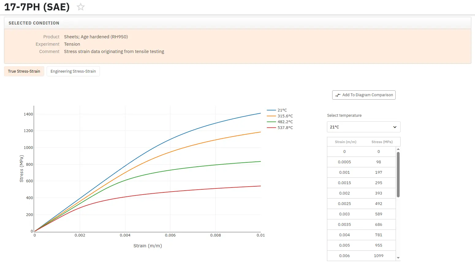
Total Materia Horizon includes a unique collection of stress-strain curves of metallic and nonmetallic materials. Both true and engineering stress curves are given, for various strain rates, heat treatments and working temperatures where applicable.
Get a FREE test account at Total Materia Horizon and join a community of over 500,000 users from more than 120 countries.