Indirect Compression Systems of Deformation
Abstract
In indirect compression an applied tensile stress induces two mutually perpendicular compressive stresses. This type of deformation allows only cold working and the two practical examples are wire drawing and deep drawing.
In wire drawing the diameter of a cylindrical piece of metal is reduced by pulling it through a tapered hole which is the internal profile of a drawing die. Deep drawing and pressing involve a combination of bending and stretching, for example the fabrication of a cup from a circular sheet blank.
In indirect compression an applied tensile stress induces two mutually perpendicular compressive stresses. This type of deformation allows only cold working and the two practical examples are wire drawing and deep drawing.
Wire Drawing
In wire drawing the diameter of a cylindrical piece of metal is reduced by pulling it through a tapered hole which is the internal profile of a drawing die. The cylindrical feed metal is initially pointed so that it protrudes through the die orifice and can be gripped for drawing.The equipment can range from a simple draw bench for intermittent drawing, to multiple draw blocks for continuous operation. The drawing block consists of three parts:
- a swift or capstan to hold the coil of rod ready for drawing,
- the die which executes the actual reduction and
- the drawing block which supplies the load and energy for reduction; it also accumulates the drawn wire in a coil form.
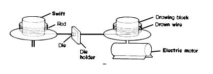
Fig.1.
There must, however, be one drawing block for each die. A continuous machine which holds five dies will also have drawing, etc. Such a machine is shown in outline in Fig.2.
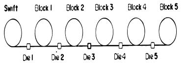
Fig.2.
Since the diameter of the wire decreases from die 1 to die 5, the velocity and length will increase proportionally. For these reasons the peripheral speed of the blocks must increase along the line. This can be achieved in one of two ways.
In the first, each drawing block is fitted with its own electric motor with fully variable-speed control which can be adjusted automatically to synchronize the block velocity to that of the wire. They suffer from the disadvantages that they are large and expensive because of the investment in and installation of costly electric equipment.
The second type of machine overcomes both of these disadvantages by making use of only one electric motor to drive a series of stepped cones. The diameters of the cones are such as to generate a sequence of peripheral speeds equivalent to a definite set of size reductions.
It is not possible to achieve the precise relationship between die and drawing block diameters which is essential in this pattern, but drawing can be carried out successfully as long as the mismatch is not too great. Mismatch results in the drawn material sliding either forwards or backwards on the blocks as they revolve. This results in friction and the evolution of heat which is dispersed by immersing the whole stepped-cone arrangement in an oil bath. They are therefore called immersed or slip machines whereas the first type is described as a non-slip machine.
The most important part of the wire drawing machine is the die. This consists of two parts, the casing and the nib. The casing is made of steel for large-diameter dies and of brass for small dies and its main function is to protect the nib. The nib which is contained inside the casing is made of tungsten carbide for large dies and industrial diamond for small. It must be made of extremely hard material since it is the part where the actual reduction is carried.
Tube Drawing
Seamless tubes are produced from blanks made by piercing or boring billets or by extrusion. The blanks are reduced in section and elongated either by passing through rolls with semicircular grooves or passes cut into them or by drawing them through dies. Drawing is most frequently used because it produces a good surface finish and close dimensional control, coupled with improved mechanical properties due to cold working.When a mandrel or plug is, used the inner and outer diameters and consequently the wall thickness are precisely defined, but with sinking only the outer diameter is controlled and the wall thickness and inner diameter depend on the stress conditions.
Sinking is normally used for small-diameter tubes where it is difficult to control the mandrel or plug. The greatest reduction per pass is achieved with mandrel drawing or sinking since friction is limited to the outer surface. In the case of plug drawing, whether it is floating or fixed, friction occurs between the outer surface and the die and also between the plug and the inner surface.
Deep Drawing and Pressing
The second indirect compression method of deforming metals is deep drawing and pressing. Both involve a combination of bending and stretching and the text will refer to deep drawing.The simplest example of this process involves the fabrication of a cup from a circular sheet blank. This is carried out using a punch and die, the sheet being drawn inwards and over the die profile by the advancing punch. The periphery of the original blank must form the top circle of the cup. This involves a large decrease in the length of the periphery and this can occur in two ways-either by wrinkling or by thickening. It is important in the deep-drawing process that the cup top is formed by metal thickening rather than by puckering and this is ensured by using a pressure ring or blank holder. Blank holders can either be of the constant-clearance or constant-pressure type.
The die can have any shape from a simple circle to the complicated assemblies required for motor-car bodies and may require a number of drawing operations. Since the blank holder prevents puckering the metal will thicken as it flows. The more it flows inwards the greater the thickening until eventually it is so thick that it "fouls" the blank holder and attempts to push it upwards. Since the holder is held rigidly and cannot raise the metal flowing inwards is "ironed" by the blank holder.
The degree of ironing increases with the rate of inward flow and this imposes large loads on the punch and the blank. The ironing load is the main factor deciding the maximum reduction possible in the deep drawing operation. This is called the Limiting Drawing Ratio and is equal to the maximum usable blank diameter divided by the die-throat diameter.
Between a and b the metal is subjected to pure radial drawing between the die and the blank holder. Stretch forming mayor may not be accompanied by thinning depending upon the ratio of the original thickness to the die radius. The larger this ratio the greater the tendency for thinning to occur. Advantage can be taken of this phenomenon to control metal thickness before it enters the throat clearance in the next stage of the process.
The metal is stretched between the die and the punch and this is accompanied by sliding along the die surface. The tendency is to decrease the clearance as a means of distributing the load more evenly over the metal in this part of the process.
An examination of the behavior of the blank during cup forming shows that it can be divided into two regions undergoes only one operation and attains its final shape and location. The remainder in the regions between passes successively through three distinct stages (radial drawing, die profile stretch forming and die throat stretching), together with a degree of ironing which increases towards the top of the cup. The final drawn cup will therefore be in a very inhomogeneous state. The base will be in the original state whilst the degree of working or deformation will increase towards the top of the cup.
Attempts have been made to produce an end product with more uniform mechanical properties by using differentially annealed blanks. This process involves using cold-worked sheets for preparing blanks by flame annealing the Tim whilst the disc is rotated. This leaves the centre in the cold-worked condition and the deep-drawing process produces a more uniform end product.
Find Instantly Precise Material Properties!
Total Materia Horizon contains mechanical and physical properties for hundreds of thousands of materials, for different temperatures, conditions and heat treatments, and much more.
Get a FREE test account at Total Materia Horizon and join a community of over 500,000 users from more than 120 countries.