Analyzing Failures of Metal Components: Part Two
Abstract
When studying a failure, great care must be used to avoid destroying important evidence. Detailed studies often require careful documentation of the service history (time, temperature, loadings and environment), supplemented by chemical analysis and electron micrographs. Further study of the sequence of events leading up to the failure, plus knowledge of the location, markings and condition of all adjacent parts after the incident, are necessary to confirm the analysis beyond reasonable doubt.
Of course, there is always the possibility of an unforeseen loading, unreported collision, or unanticipated vibration that may develop to cause premature failure. These factors may usually be diagnosed by careful examination and gathering of facts.
Analysis of failure
When studying a failure, great care must be used to avoid destroying important evidence. Detailed studies often require careful documentation of the service history (time, temperature, loadings and environment), supplemented by chemical analysis and electron micrographs. Further study of the sequence of events leading up to the failure, plus knowledge of the location, markings and condition of all adjacent parts after the incident, are necessary to confirm the analysis beyond reasonable doubt.
Of course, there is always the possibility of an unforeseen loading, unreported collision, or unanticipated vibration that may develop to cause premature failure. These factors may usually be diagnosed by careful examination and gathering of facts.
As supplementary information, we have appended a list of classifications as to cause of failure, and general guidelines to be following in determining the major cause or causes.
Initial Observations. Make a detailed study by visual inspection of the actual component that failed, preferably at the failure site as soon after the failure as possible. Profuse color photographs are essential to record every detail for later review.
Background Data. Gather all available data concerned with specifications and drawings, component design, fabrication, repairs, maintenance and service use. Concentration on obtaining facts pertinent to all possible failure modes is essential. Particular attention to environmental details, including normal service loads (as well as accidental overloads and cyclic loading) and resulting stress, temperature variations and gradients are desirable.
Supplementary Laboratory Studies. Make tests to verify that the material in the component actually possesses the specified composition, dimensions, processing and properties. Supplementary studies may be needed (for example, composition of corrosion products, simulated service or environmental tests, stress analysis, determination of microstructure and development of cracks, dynamic strain measurements, elevated or low temperature tests and surface replicas) to define the factors which contributed to the failure. Electron probe X-ray analysis can be useful in examining inclusions, microsegregation, or the composition of oxide or surface contaminants.
Frequently, examination of a fracture face with a low-power binocular microscope can reveal the type and cause of failure. However, the observer must be familiar with a wide variety of fracture textures, and be able to approach the examination without a preconceived idea of the cause for the fracture. Further confirmation can often be obtained by studies of cracks and structures at higher magnification, using small samples from the regions of failure.
Synthesis of Failure. List not only all positive facts and evidence, but also all the negative responses to the questions that may be asked about the failure. Sometimes it is important to know that specific things did not happen or certain evidence did not appear to determine what could have happened. From a tabulation of these data, the actual failure should be synthesized to include all available items of the evidence.
The cause will usually be classified in one of the categories outlined in the following list, and corrective action or applied research guidance can be recommended. Appropriate solutions may involve redesign, change of alloy and/or processing, quality control, protection against environment, changes in maintenance schedules, or restrictions on service loads or service life.
Classification of Failure Causes
Failures Due to Faulty Processing
- Flaws due to faulty composition (inclusions, embrittling impurities, wrong material).
- Defects originating in ingot making and casting (segregation, unsoundness, porosity, pipes, nonmetallic inclusions).
- Defects due to working (laps, seams, shatter cracks, hot-short splits, delamination, and excess local plastic deformation).
- Irregularities and mistakes due to machining, grinding, or stamping (gouges, burns, tearing, fins, cracks, embrittlement).
- Defects due to welding (porosity, undercuts, cracks, residual stress and lack of penetration, under bead cracking, heat affected zone).
- Abnormalities due to heat treating (overheating, burning, quench cracking, grain growth, excessive retained austenite, decarburization, precipitation).
- Flaws due to case hardening (intergranular carbides, soft core and wrong heat cycles).
- Defects due to surface treatments (cleaning, plating, coating, chemical diffusion, hydrogen embrittlement).
- Careless assembly (mismatch of mating parts, entrained dirt or abrasive, residual stress, gouges or injury to parts and the like).
- Parting line failures in forging due to poor transverse properties.
Failures due to Faulty Design Considerations or Misapplication of Material
- Ductile failure (excess deformation, elastic or plastic; tearing or shear fracture).
- Brittle fracture (from flaw or stress raiser of critical size).
- Fatigue failure (load cycling, strain cycling, thermal cycling, corrosion fatigue, rolling contact fatigue, fretting fatigue).
- High-temperature failure (creep, oxidation, local melting, warping).
- Static delayed fractures (hydrogen embrittlement, caustic embrittlement, environmentally stimulated slow growth of flaws).
- Excessively severe stress raisers inherent in the design.
- Inadequate stress analysis, or impossibility of a rational stress calculation in a complex part.
- Mistake in designing on basis of static tensile properties, instead of the significant material properties that measure the resistance of the material to each possible failure mode.
Failure Due to Deterioration During Service- Conditions
- Overload or unforeseen loading conditions.
- Wear (erosion, galling, seizing, gouging, cavitations).
- Corrosion (including chemical attack, stress corrosion, corrosion fatigue), dezincification, graphitization of cast iron, contamination by atmosphere.
- Inadequate or misdirected maintenance or improper repair (welding, grinding, punching holes, cold straightening, and so forth).
- Disintegration due to chemical attack or attack by liquid metals or platings at elevated temperatures.
- Radiation damage (sometimes must decontaminate for examination which may destroy vital evidence of cause of failure), varies with time, temperature, environment and dosage.
- Accidental conditions (abnormal operating temperatures, severe vibration, sonic vibrations, impact or unforeseen collisions, ablation, thermal shock and so forth).
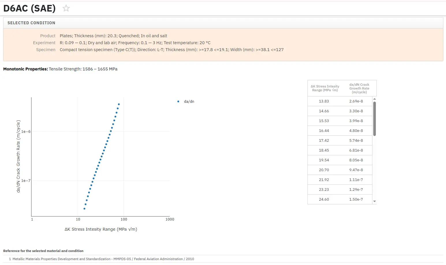
Access Fracture Mechanics Properties of Thousands of Materials Now!
Total Materia Horizon includes a unique collection of fracture mechanics properties such as K1C, KC, crack growth and Paris law parameters, for thousands of metal alloys and heat treatments.
Get a FREE test account at Total Materia Horizon and join a community of over 500,000 users from more than 120 countries.