Cast steel: Microstructure and grain size
Abstract
The equilibrium diagram does not tell us what form is taken by the ferrite or cementite ejected from the austenite on cooling. Without going too deeply into the matter, it may be considered that the ferrite has a choice of three different positions, which, in order of degree of supercooling or ease of forming nuclei, are:
1) boundaries of the austenite crystals;
2) certain crystal planes (octahedral);
3) about inclusions.
The equilibrium diagram does not tell us what form is taken by the ferrite or cementite ejected from the austenite on cooling. Without going too deeply into the matter, it may be considered that the ferrite has a choice of three different positions, which, in order of degree of supercooling or ease of forming nuclei, are:
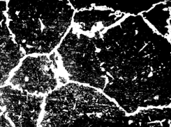
(1) boundaries of the austenite crystals; (Fig. 1)
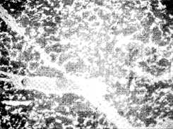
(2) certain crystal planes (octahedral); (Fig. 2)
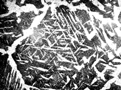
(3) about inclusions (Fig. 3).
 |  |
| Figure 1. | Figure 2. |
 | |
| Figure 3. |
Thus, ferrite starts to form at the grain boundaries, and if sufficient time is allowed for the diffusion phenomena a ferrite network structure is formed, while the pearlite occupies the centre, as in Fig. 1. The size of the austenite grains existing above A3 is thereby betrayed.
If the rate of cooling is faster, the complete separation of the ferrite at the boundaries of large austenite grains is not possible, and ejection takes place within the crystal along certain planes, forming a mesh-like arrangement known as a Widmanstätten structure, shown in Fig. 2. In steels containing more than 0,9% carbon, cementite can separate in a similar way and Widmanstätten structures are also found in other alloy systems.
Steel with Widmanstätten structures are characterised by (1) low impact value, (2) low percentage elongation since the strong pearlite is isolated in ineffective patches by either weak ferrite or brittle cementite, along which cracks can be readily propagated. This structure is found in overheated steels and cast steel, but the high silicon used in steel castings modifies.
It is highly desirable that Widmanstätten and coarse network structures generally be avoided, and as these partly depend upon the size of the original austenite grain, the methods of securing small grains are of importance. Large austenite grains may be refined by (a) hot working, (b) normalising.
Such refined austenite grains are liable to coarsen when the steel is heated well above the Ac3 temperature, in such operations as welding, forging and carburising unless the grain growth is restrained. This restraint can be brought about by a suitable mode of manufacture of the steel.
Controlled grain size
It is now possible to produce two steels of practically identical analysis with inherently different grain growth characteristics so that at a given temperature each steel has an "inherent austenite grain size", one being fine relative to the other. The so-called "fine-graine" steel increases its size on heating above Ac3 but the temperature at which the grain size becomes relatively coarse is definitely higher than that at which a "coarse-grained" steel develops a similar size.
The fine-grained steels are "killed" with silicon together with a slight excess of aluminium which forms aluminium nitride as submicroscopic particles that obstruct austenite grain growth and is an example of a general phenomenon.
At the coarsening temperature the AIN goes into solution rapidly above 1200°C and virtually completely at 1350°C. The austenite grain size is frequently estimated by the following tests:
(1) McQuaid-Ehn Test. Micro-sections of structural steels carburised for not less than 8 hours at 925°C and slowly cooled to show cementite networks are photographed at a magnification of 100. Comparison is made with a grain-size chart issued by the American Society for Testing Materials. This test is also valuable in detecting "abnormality" of pearlite.
(2) The Quench and Fracture test consists in heating normalised sections of the steel, above Ac3 quenching them at intervals of 30°C. An examination of the fractured surface enables the depth of hardness and grain size to be estimated by comparison with standard frac tures.
Find Instantly Precise Properties of Cast Materials!
Total Materia Horizon contains property information for thousands of cast materials: composition, mechanical and physical properties, nonlinear properties and much more.

Get a FREE test account at Total Materia Horizon and join a community of over 500,000 users from more than 120 countries.