Steel Rolling
Abstract
Steel rolling is the most widely used metal deformation process, functioning as an indirect compression technique where radial pressure from rolls deforms metal and pulls it through the roll gap. Unlike traditional compression or forging, rolling occurs continuously between roll pairs at various inclinations. The process encompasses multiple mill configurations including two-high, three-high, four-high, and cluster mills, each designed for specific applications from primary rolling to precision foil production. Rolling mill design considerations include roll bending prevention, load optimization, and elastic deformation management. Modern developments incorporate hydraulic roll adjustment systems and interstand tension control for superior shape control and surface quality in continuous strip production.
Introduction to Steel Rolling Technology
Rolling represents an indirect compression process that has become the cornerstone of modern metal manufacturing. The fundamental principle involves applying radial pressure from rolls to deform metal and pull it through the roll gap in a continuous motion. This process differs significantly from traditional compression or forging methods in two critical aspects: the compression occurs between roll pairs positioned at various inclinations, and the operation maintains continuity throughout the deformation cycle.
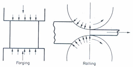
Figure 1: Basic rolling process mechanism
The widespread adoption of rolling technology stems from its exceptional versatility and efficiency in metal processing. Due to the numerous variations available, rolling processes require their own comprehensive classification system based on roll arrangement within mill stands and the sequential arrangement of stands themselves.
Rolling Mill Classifications and Configurations
Two-High Rolling Mills
The two-high mill represents the earliest and simplest rolling mill design. However, production rates typically remain low due to time losses associated with returning metal to the mill's front position. This limitation led to the development of reversing two-high mills, which allow metal rolling in both directions. Despite this improvement, reversing mills face constraints in handling length capabilities, and increased rolling speeds yield minimal output improvements due to extended time requirements for rotation reversal at each pass. Economic considerations establish a practical maximum length of approximately 10 meters for this configuration.
Three-High Rolling Mill Systems
The three-high mill emerged as the logical evolution, combining advantages of both reversing and non-reversing two-high mills. This configuration requires elevating tables on both roll sides to facilitate operation. A significant limitation of three-high mills involves the inability to adjust roll gaps between passes, necessitating grooves or passes cut into roll faces to achieve varying pass reductions.
Advanced Rolling Mill Designs
All traditional mill types share a common disadvantage: all rolling stages occur on the same rolled surface, resulting in compromised surface quality. Roll changes on these mills occur frequently and consume considerable time. Consequently, these mill types primarily serve primary rolling applications where rapid shape changes take priority over surface quality considerations.
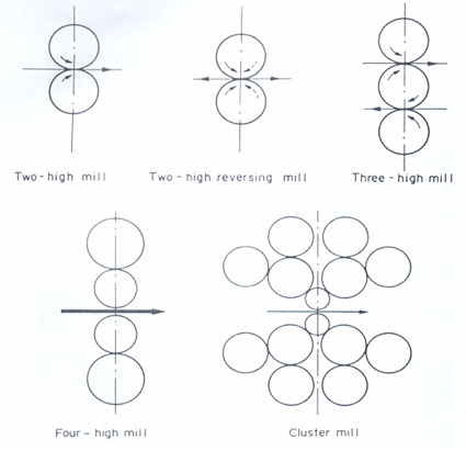
Figure 2: Classification of different rolling mill types
Four-High Mills and Cluster Mill Technology
Four-high mills represent a specialized variant of two-high mills, designed to reduce rolling loads through decreased work roll diameter. However, this design introduces roll bending risks, which are mitigated by supporting small work rolls with larger backing rolls. The backing roll diameter cannot exceed 2-3 times the work roll diameter, and as work roll diameters decrease to accommodate extremely high rolling loads, backing roll sizes must correspondingly decrease. Eventually, backing rolls themselves require support, leading to the ultimate design solution: the cluster mill.
The traditional mill design faces criticism due to its inherent roll bending tendency based on beam principle mechanics. Sendzimir proposed an innovative design eliminating this limitation through the castor principle, where work rolls receive support across their entire face via backing roll arrays. This principle enables installations capable of rolling stainless steel 1600mm wide using work rolls with 85mm diameters.
Continuous Rolling Mill Operations
Continuous rolling mills classify according to stand or pass arrangements. In-line arrangements characterize continuous mills, while line-abreast configurations define looping or cross-country mills. Looping and cross-country mills require workpiece bending or turning between stands, making them suitable for rod, rail, or section rolling. Continuous mills serve plate, strip, or sheet production. All continuous mill configurations demand substantial capital investment and require guaranteed large product demand for economic justification.
Rolling Load Mechanics and Friction Forces
The friction force derivation reveals complex mechanical interactions during rolling. Pressure acts radially on element ends, and elements located between entry points and neutral points experience frictional forces directed toward neutral points. Radial pressure generates horizontal components that tend to reject metal and prevent roll entry, while friction forces create horizontal components dragging metal inward. Metal passage through rolls depends upon the relative values of these horizontal force components.
Primary Rolling vs. Precision Rolling Applications
Primary rolling processes require large maximum reductions to enable rapid and economical metal deformation. Primary mills utilize large diameter rolls with roughened or ragged surfaces to increase friction coefficients. Conversely, rolling load minimization requires the smallest possible radius and smoothest possible roll surfaces. This principle guides cluster mill design for extensive foil rolling applications, featuring small work rolls supported by larger back-up rolls to prevent bending. Even with cluster mills, excessive rolling loads may necessitate front and back tension devices applied to the metal during rolling.
Foil rolling and finishing mills differ substantially from primary mills, which utilize large diameter rolls with roughened surfaces for maximum material reduction capabilities.
Elastic Deformation in Rolling Operations
Metal deformation processes require tools to remain elastically loaded while workpieces flow plastically. Although elastic deformation typically remains negligible, rolling presents exceptions due to two factors. First, rolling loads and stresses can achieve extreme magnitudes, particularly with thin, work-hardened workpieces. Second, rolling tools comprise entire mill assemblies including rolls and housing with overall dimensions measured in meters. This combination can produce substantial elastic deformation strains distributed among mill stand extension (mill spring), roll flattening, and roll bending.
Roll Flattening Phenomena
Roll flattening occurs when workpieces passing between roll pairs experience compression from radial stress, with reactions transferring to mill bearings and housing systems with limited yield capacity due to their substantial dimensions. Attempts to compress thin, hard materials further generate reactions so large that rolls deform elastically, increasing the contact arc's radius of curvature. Flattening extent depends on reaction stress magnitude and roll elastic constants.
Roll flattening establishes minimum gauge limitations for specific mills. Attempts to roll below this threshold result in greater roll deformation without strip plastic deformation. With thin gauges, friction hills become substantial, producing contact arc reaction stresses exceeding roll yield stress, making roll deformation easier than metal deformation. Operating mills maintain circular roll geometry, but static loads without removal during shutdown cause surface flattening over roll contact areas.
Roll Bending Prevention and Shape Control
Efforts to avoid or limit roll bending focus on rolling load reduction through small work rolls and four-high mill implementations. Even with these mills, roll bending occurs and requires accommodation through roll cambering (barrel shaping). Multistand continuous rolling employs interstand tension adjustment to maintain constant rolling loads and achieve flat surfaces, representing crucial strip shape control aspects.
Recent developments include hydraulic jack introduction onto roll necks, enabling roll camber alteration through active roll bending. Initial results indicate exceptional success potential for strip shape control applications.
Previously described methods involve continuous rolling with front, back, or interstand tension capabilities. Single sheet rolling cannot utilize these load control techniques, necessitating alternative shape control approaches.
Mill Spring and Structural Considerations
Mill spring or plastic distortion relates to roll separating force reactions. Without mill housing constraint, rolls would separate, preventing metal reduction. Upper rolls push housing tops upward while bottom rolls push housing bases downward, subjecting housing to tensile stress below cast steel yield stress but creating measurable elastic deformation.
Deformation extent depends on rolling load magnitude, housing cross-sectional area, and housing height. Small deformation extent characterizes hard or rigid mills, while large deformation indicates soft or springy mills.
Mill characteristics can be determined by setting constant roll gaps and rolling different metal pieces producing varying rolling loads through different gauge materials or metal types. Graphing rolling load versus gauge relationships, with gauge measurements from rolled piece thickness, establishes mill spring characteristics for operational optimization.
Access Precise Properties of Structural Steels Now!
Total Materia Horizon contains property information for 150,000+ structural steels: composition, mechanical and physical properties, nonlinear properties and much more.
Get a FREE test account at Total Materia Horizon and join a community of over 500,000 users from more than 120 countries.