Fracture Toughness of Tool Steels: Part Two
Abstract
Even under the most controlled limits, tool steels have operational limits which can exist in the material or arise during the first production years of use.
The increased use of ultra-high strength steels (UHSS) in car bodies has led to significant further study on how to understand what factors control fatigue properties, ductility and ultimately fracture toughness.
Tool steels are special materials designed to function and perform different tasks in accordance to design specifications. However, even in the most controlled environment and applied operational control, each type of tool steel has its operational limits. These limitations which could preexist in the material or arise during the service year of the tool can cause the shortening of the tool life and in some cases cause a catastrophic failure.
Production of tool steels is either performed by conventional casting, powder metallurgy (PM) or spray forming (SF). With conventional casting the steel melt is teemed into large ingot molds of approximately 1-2 m3 were it slowly cools into solid material. With PM the steel melt is atomized by an inert gas into small droplets, which solidify immediately, when sprayed into a collecting container. Thereafter the powder is compacted under high pressure, > 100 bars, forming solid cylinders. The SF process is similar to PM, though here the steel droplets has not totally solidified, instead the material is sprayed onto a rotating disc producing a solid cylinder, thereby making the high-pressure process step of PM unnecessary.
Conventional casting is the major production route used, which could be followed by a process called electro slag refining/re-melting (ESR) where the non-metallic inclusion content is lowered. Conventional casting has a lower production cost per unit than the other two processing routes. The disadvantage though is a more heterogeneous material, due to segregation in the order of mm and even cm, with respect to mechanical properties.
With PM materials segregation is determined by the size of the powder spheres, which normally are around 100 µm in diameter. Thereby mechanical properties become much more homogeneous compared to conventional cast materials. SF materials are similar to PM materials though the microstructure becomes slightly coarser compared to PM but the cost is lower. With some exceptions, similar alloy contents could be used in all production routes, though resulting in different mechanical properties caused by different microstructures.
A large effort of research of tool steels today is to improve and understand what controls fatigue properties, ductility and fracture toughness. This is driven by the increased use of ultra-high strength steels (UHSS) in car bodies. With UHSS thinner panels with equal strength as in previously used thicker steel panels could be used to reduce weight and thereby reduce environmental impact. UHSS undergoes deformation hardening when pressed into the desired form. This further increases the mechanical impact on the tool steel used for pressing.
The aim of work Bressan D. et al was to develop an appropriate fracture test methodology and to obtain experimentally the fracture toughness of AISI D6 steel as received and with a specific heat treatment. Therefore, the focus was to investigate the influence of the heat treatment on fracture toughness and to examine the associated fracture mechanisms.
Manufacturing the SENB specimen follows the ASTM E 399 specifications and presents three main dimensional characteristics: total crack length (a) to be pre-generated by fatigue, thickness (b) and high (h); being h=2b and a/h= 0.45 to 0.55. Figure 1 shows the SENB specimen with the main dimensional values. Initially, a groove with depth of 3 mm has been machined in the middle section of the specimen and later another groove of 1 mm depth by 0.3 mm width has been performed by wire electro-erosion machine at the bottom of the initial groove in order to guarantee the generation of a perpendicular crack. After that, the specimen was assembled in the pre-cracking machine and a fatigue crack was grown by cyclic three point bending. The applied load was regulated through the adjustment of the beam central deflection, in order to avoid premature rupture. The total crack length had to be between 9.9 mm and 11 mm. Two lines in the specimen lateral face were drawn to monitor visually the crack length during the pre-cracking operation.
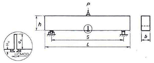
Figure 1: Three point bending test in a notched prismatic beam and its geometry: S = 88 mm; L = 90 mm; b = 11 mm; h = 22 mm, ao ~ 4 mm; Ho= 2 mm
Following this, the SENB specimen was assembled in a universal tensile testing machine equipped with a load cell of 2 ton capacity, made by EMIC. AISI D6 tool steel was tested in two conditions: as received and with heat treatment. The heat treatment was quenching followed by a two tempering process. For each condition, 10 specimens have been prepared. However, some have ruptured in the pre-cracking operation. Table 1 below presents the heat treatment and the mechanical properties of AISI D6 steel grade.
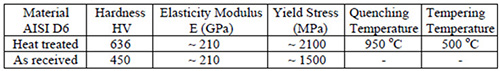
Table 1: AISI D6 mechanical properties and heat treatment temperatures
In Figure 2, the experimental result of one SENB specimen in three point bending, according to the ASTM E 561 is shown. The linear increase in the stress intensity parameter KR for ductile fracture of AISI D6 as received in function of stable crack growth is observed. The fracture toughness parameter KIC was obtained from the curve at the point that corresponds to the crack growth Δa = 2% ao.
On the basis of the data presented in work, it may be assumed that the fracture toughness of heat treated AISI D6 tool steel has dropped to 25.9 MPa.m1/2 compared with 44 MPa.m1/2 before heat treatment (Figures 3 and 4). Thus, heat treatment increased the yield stress by 40%, but decreased toughness by about 50%. Fracture mechanism in the fast region of heat treated AISI D6 is due to transgranular fracture.
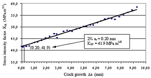
Figure 2: Stress intensity factor KR as function of stable crack growth for AISI D6 tool steel as received. KIC is at point Δa = 2% ao
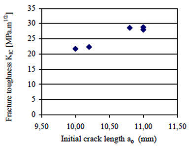
Figure 3: Heat treated AISI D6 tool steel
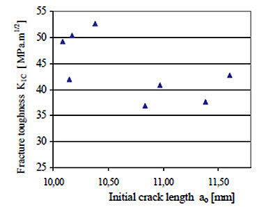
Figure 4: As received AISI D6 tool steel
Access Fracture Mechanics Properties of Thousands of Materials Now!
Total Materia Horizon includes a unique collection of fracture mechanics properties such as K1C, KC, crack growth and Paris law parameters, for thousands of metal alloys and heat treatments.
Get a FREE test account at Total Materia Horizon and join a community of over 500,000 users from more than 120 countries.