Fracture
Abstract
Most alloys contain second phases which lose cohesion with the matrix or fracture and the voids so formed grow as dislocations flow into them. Coalescence of the voids forms a continuous fracture surface followed by failure of the remaining annulus of material usually on plane at 45° to the tension axis. The central fracture surface consists of numerous cup-like depressions generally called dimples. The shape of the dimples is strongly influenced by the direction of major stresses-circular in pure tension and parabolic under shear
Ductile fracture
A pure and inclusion free metal can elongate under tension to give approx. 100% RA and a point fracture, Fig. 1. Most alloys contain second phases which lose cohesion with the matrix or fracture and the voids so formed grow as dislocations flow into them. Coalescence of the voids forms a continuous fracture surface followed by failure of the remaining annulus of material usually on plane at 45° to the tension axis. The central fracture surface consists of numerous cup-like depressions generally called dimples. The shape of the dimples is strongly influenced by the direction of major stresses-circular in pure tension and parabolic under shear. Dimple size depends largely on the number of inclusion sites. Fig. 2a shows typical dimples.
| Figure 1. | (a) Stages in ductile fracture from inclusions |
| (b) Fracture toughness n thickness |
Some important features of ductile fracture can be summarised as follows:
- Pure metals and solid solutions that are relatively free from second phase particles (including impurity particles) are usually more ductile than strong two-phase alloys.
- The local stress required for whole nucleation at particles depends on their resistance to cracking and the strength of their bond with the matrix.
- The local stress generated at the particles depends on the flow strength of the alloy, the applied strain and the shape and size of the particles.
- Growth of the holes, so that they coalesce to form a macroscopic fracture, depends on the applied stresses being tensile. Much higher ductilities are achieved in compressive straining.
In cleavage fracture the material fails along well defined crystallographic planes within the grain but the crack path is affected by grain boundaries and inclusions. Basically a cleavage fracture surface contains large smooth areas separated by cleavage steps and feathers, river markings and cleavage tongues which are the direct result of crack path disturbances-Fig. 2b.
Intercrystalline fracture is characterized by separation of the grains to reveal a surface composed of grain boundary facets, Fig. 2c. This type of fracture is found in stress-corrosion, creep hot tearing and hydrogen embrittlement.
Fatigue fractures are characterized by striations (Fig. 2d) representing the extent of crack propagation under each cycle of loading.
 |  |
| a) Dimples in a ductile fracture of mild steel (x5000) | b) Cleavage patterns in HS steel fracture (x12000) |
 |  |
| c) Intergranular fracture in low alloy steel (x1500) | d) Fatigue striations in Nimonic 80A (x7000)(A.Strang) |
Compound stresses and brittle fracture
The failure of some American all-welded ships during the Second World War has stimulated much work on the causes of brittle fracture in steel. In the tensile test plastic deformation involves shearing slip along crystal planes within the crystals, but in the presence of tension of equal magnitude in each principal direction, shearing stresses are absent, plastic deformation is prevented and a brittle fracture occurs as soon as the cohesive strength of the material is exceeded. Equal triaxial tension stresses do not arise frequently in practice, but it is common to find a triaxial tension superimposed on a unidirectional tension, and if the margin between cohesive strength and plastic yield strength is small, a brittle fracture may occur in a material ordinarily considered highly ductile. Compound stresses arise in a weld in very thick plate and in a tube under internal pressure and an axial tension.
This is shown in Fig. 3 with cohesive stress-strain curves, B, N, and F. If the two curves intersect at Y, brittle fracture occurs preceded by plastic deformation, which decreases as the cohesive strength curve becomes lower with respect to the yield stress-strain curve. Orowan has shown that if the yield stress is denoted by Y, the strength for brittle fracture by B (both Y and B depend on the plastic strain), and the initial value of Y (for strain = 0) by Y0 we have the following relation:
- The material is brittle if B < Y0;
- The material is ductile but notch-brittle if Y0 < B < 3Y0
- The material is not notch-brittle if 3Y < B.
The factor 3 takes into account the stress increase at a notch. Whether the material is notch-brittle or not depends on the very small margin between B and 3Y.
| Figure 3. | (a) Yield and cohesive stress curves |
| (b) Slow notch bend test | |
| (c) Effect of temperature on the Izod value of mild steel |
Carbon steel is an exceptional material, because 3Y and B are so close, and this is the reason why the results of Izod tests seem to be so erratic, and why notch brittleness is so sensitive to slight variations of composition, previous treatment and temperature.
Brittle fracture is characterised by the very small amount of work absorbed and by a crystalline appearance of the surfaces of fracture, often with a chevron pattern pointing to the origin of fracture, due to the formation of discontinuous cleavage cracks which join up (Fig. 4). It can occur at a low stress of 75-120 MPa with great suddenness; the velocity of crack propagation is probably not far from that of sound in the material in this type of fracture plastic deformation is very small, and the crack need not open up considerably in order to propagate, as is necessary with a ductile failure.
The work required to propagate a crack is given by Griffith`s formula:
 | (1) |
where:
s = tensile stress required to propagate a crack of length c
g = surface energy of fracture faces
E = Young`s modulus
Orowan modified the Griffith theory to include a plastic strain energy factor, p, since some plastic flow is always found near the fracture surface:
 | (2) |
When the temperature is above the brittle-ductile transition temperature, p is large and the stress, s, required to make the crack grow will also be large. Below the transition temperature the metal is brittle and p will be smaller. The stress necessary to cause crack growth, therefore, will be reduced. The reason for the increasing speed of crack propagation, once a crack has started, is clear from both Griffith`s and Orowan`s equations: as the crack grows in length, the stress required for propagation continually decreases.
Access Fracture Mechanics Properties of Thousands of Materials Now!
Total Materia Horizon includes a unique collection of fracture mechanics properties such as K1C, KC, crack growth and Paris law parameters, for thousands of metal alloys and heat treatments.
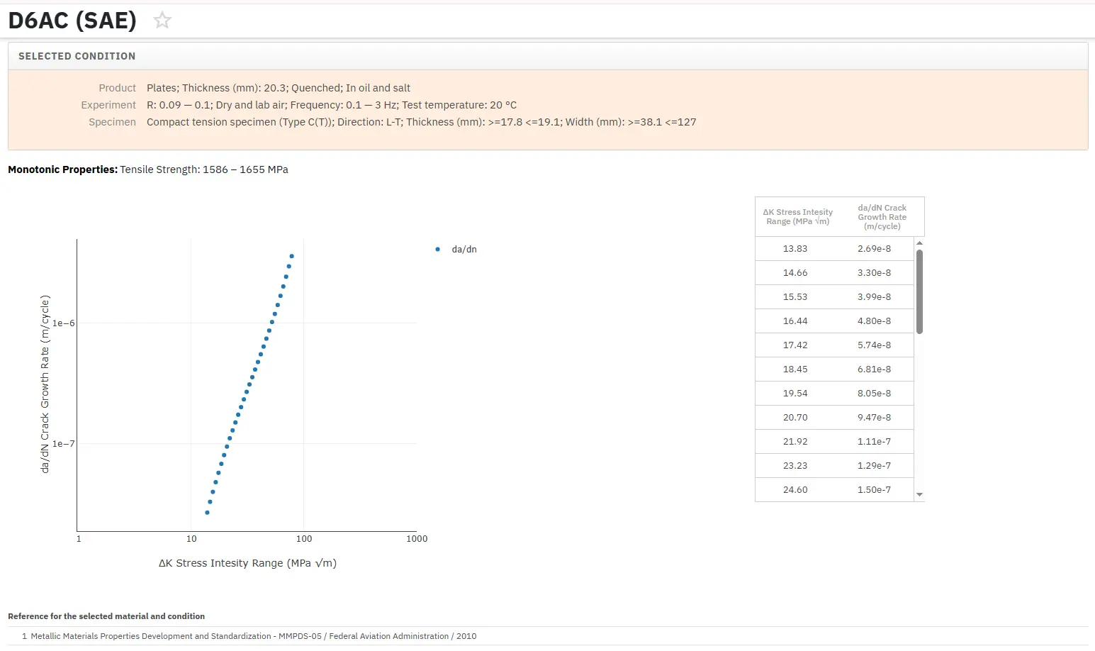
Get a FREE test account at Total Materia Horizon and join a community of over 500,000 users from more than 120 countries.