Production of Creep-Resistant Steels for Turbines: Part Two
Abstract
Vacuum Arc Remelting (VAR) is a secondary melting process used in the production of metal ingots with a precise chemical and mechanical homogeneity for highly demanding applications. Ingots derived from the VAR process are typically utilized in the production of the critical components of jet engines and industrial gas turbines, as well as for military applications and heavy industry.
Vacuum Arc Remelting (VAR) Process
The VAR process is primarily used in applications where purity and homogeneity are essential for the finished product quality. Therefore, the electrodes used in the VAR process are arc melted in a water cooled crucible inside a vacuum chamber to ensure they possess the physical characteristics to maintain the required purity and remelting consistency for the production of creep resistant steel.
In contrast to the ESR (Electro Slag Remelting) process, the refining of molten steel cannot proceed unless the desired electrode characteristics have been achieved. Figure 1 shows a schematic diagram of the VAR equipment.
Another comparison between VAR and ESR is the relative cooling rates between the two processes. Molten steel cools down at a faster rate through the VAR process yielding a higher quality product through superior solidification and reduced segregation. As described there are some clear advantages of the VAR process in the production of superalloys however due to the physical constraints of using a vacuum chamber the capacity and therefore yields of the VAR process are limited in comparison to ESR.
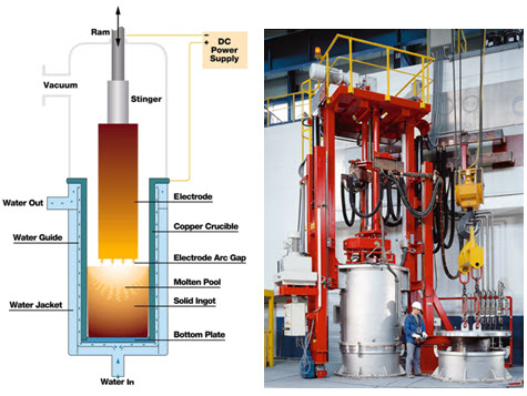
Figure 1: Schematic of the VAR furnace
Vacuum Arc Remelting (VAR) is a secondary melting process used in the production of metal ingots with a precise chemical and mechanical homogeneity for highly demanding applications. Ingots derived from the VAR process are typically utilized in the production of the critical components of jet engines and industrial gas turbines, as well as for military applications and heavy industry. The nature of such applications often demand specific and precise material properties to ensure the finished product specifications are met. Common examples of such materials are Ni or Ti-based super alloys and highly alloyed steels.
One of the most significant problems of Vacuum Arc Remelting (VAR) is the lack of chemical homogeneity in the ingots that are produced. Previous mathematical studies of the VAR process have demonstrated that the characteristics of the mushy zone (the interaction of liquid and solid in the same zone) are the key factors defining the severity and the characteristics of macro-segregation in the produced ingots.
Thus, a new mathematical model of the complete VAR process was developed, capable of representing two distinctive morphologies of the mushy zone. (1) A rigid columnar structure and slurry of free floating equiaxed grains is introduced. (2) A model accompanied by a simple criterion for the columnar-to-equiaxed transition allows the capture of segregation defects induced by motion and settling of equiaxed grains.
In addition to the described morphological models, the mathematical simulations needed to include studies of two distinctive flow regimes in VAR. (1) Weak Buoyancy driven flow and (2) Strong Lorentz driven flow. The results demonstrate a swift transition from weak buoyancy driven flow to strong electromagnetically driven flow in the presence of an increasing arc current.
The shift of flow regime to a strong electromagnetically driven state results in a relative increase of macro-segregation and thus is not desirable. The key to understanding the speed of the transition between flow regimes is in the instabilities of the thermal stratification within liquid pool at the early stages of the VAR process.
Mathematical models are also used for the study of macro-segregation evolution during multiple VAR melts (when the ingot of the previous melt is used as a source material for the next melt). The study results demonstrate that the increase of micro-segregation during a sequence of multiple melts mostly occurs due to the increase of ingot radius, and not the non-uniformity in electrode composition. In some instances however, nonuniform electrode composition may result in substantial additional buoyancy forces in the liquid pool, thus affecting the final ingot macrosegregation
Vacuum Induction Melting (VIM) Process
The VIM process involves using a melting furnace to melt raw materials by electromagnetic induction while under vacuum. Since refining does not result from the VIM process, it is essential that the raw materials (ferroalloys and metals depending on the application) should be of extremely high purity. Although application to large steel forging products is quite limited, the process coupled with VAR/ESR processes is indispensable for the production of super alloys with exacting product specifications.
The VIM Process was specifically developed for the processing of specialized and exotic alloys. As the requirement for specialized materials rises this methodology is becoming more common throughout the industry. VIM was developed to melt and cast super alloys and high-strength steels, many of which require vacuum processing because they contain refractory and reactive elements such as Ti, Nb and Al. It can also be used for stainless steels and other metals when a high-quality initial melt is required.
As the name suggests, the process involves melting of a metal under vacuum conditions in conjunction with electromagnetic induction. The Electromagnetic induction process is used to create electrical eddy currents (via the induction coil) in the metal and the subsequent result of the heated charge is to melt the metal.
The furnace consists of an airtight, water-cooled steel jacket capable of withstanding the required vacuum for processing. The metal is melted in a crucible housed in a water-cooled induction coil, and the furnace is typically equiped with a suitable refractory lining.
Metals and alloys that have a high affinity for gases, in particular nitrogen and oxygen, are often melted/refined in vacuum induction furnaces to prevent contamination with these gases.
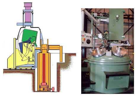
Figure 2: Vacuum induction furnace
Access Creep Properties of Thousands of Materials Now!
Total Materia Horizon includes the largest database of creep data such as yield stress and creep rupture strength at different temperatures, for thousands of metallic alloys and polymers.
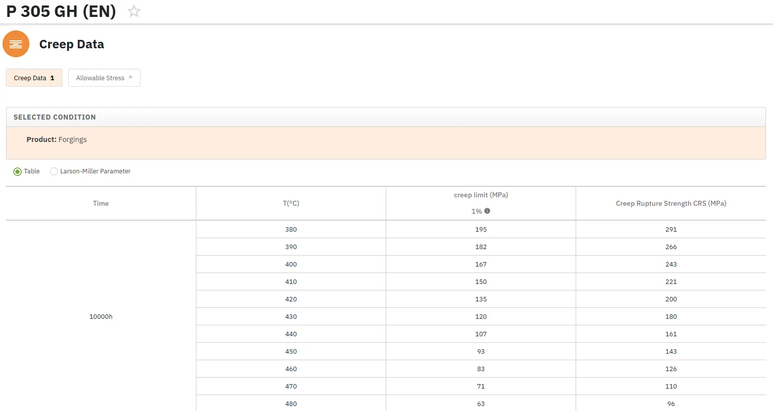
Get a FREE test account at Total Materia Horizon and join a community of over 500,000 users from more than 120 countries.