Fracture Toughness : Part Two
Abstract
For cases where the plastic energy at the crack tip is not negligible, other fracture mechanic models, such as the J integral or R-curve, can be used to characterize a material.
Stress intensity factor K can be considered as a stress-based estimate of fracture toughness.
When a test fails to meet the thickness and other test requirements that are in place to insure plane-strain condition, the fracture toughness values produced are represented by the designation KC. Sometimes it is not possible to produce a specimen that meets the thickness requirement. For example when a relatively thin plate product with high toughness is being tested, it might not be possible to produce a thicker specimen with the desired plain-strain conditions at the crack tip.
For cases where the plastic energy at the crack tip is not negligible, other fracture mechanic models, such as the J integral or R-curve, can be used to characterize a material. The toughness data produced by these other tests will be dependent on the thickness of the product tested but will not be classed as a true material property.
However, plane-strain conditions do not exist in all structural configurations and using KIC values in the design of relatively thin areas may result in excess conservatism and therefore, a weight or cost penalty. In cases where the actual stress state is plane-stress or, more generally, an intermediate or transitional-stress state, it is more appropriate to use J integral or R-curve data, which are appropriate for slow, stable fractures (ductile tearing) rather than a rapid (brittle) fracture.
Parameters Obtained From Testing
The following are the fracture toughness parameters commonly obtained from testing.
Stress intensity factor K can be considered as a stress-based estimate of fracture toughness. As mentioned before, it is derived from a function which depends on the applied force at fracture. K depends on geometry (the flaw depth, together with a geometric function, which is given in test standards for the geometry of each test specimen).
Depending on the direction of the specimen loading and the specimen thickness, four types of stress-intensity factor are used: KC, KIC KIIC KIIIC.
KC is the stress-intensity factor of a specimen (or fracture toughness), of which the thickness is less than a critical value. KC is therefore dependent on the specimen thickness. This condition is called plane stress.
KIC, KIIC and KIIIC are stress-intensity factors also relating to the specimen thickness, but are apparent only as the thickness moves above a critical value. As this happens the values of KIC KIIC KIIIC cease to depend on the specimen thickness, and transitions into to the condition called plane strain.
KIC is used for the estimation of the critical stress applied to a specimen with a given crack length
where :
KIC – stress-intensity factor, measured in MPa*m½;
σC – the critical stress applied to the specimen;
a – the crack length for edge crack or half crack length for internal crack;
Y – geometry factor
Crack-tip opening displacement CTOD or σ can be considered as a strain-based estimate of fracture toughness. However, it can be separated into elastic and plastic components.
The elastic component of CTOD is derived from the stress intensity factor, K. In some standards, the plastic component of CTOD is obtained by assuming that the specimen rotates about a plastic hinge.
The plastic component is derived from the crack mouth opening displacement (measured using a clip gauge). The position of the plastic hinge (defined by rp) is given in test standards for each specimen type. Alternative methods exist for estimating CTOD, which make no assumption regarding the position of the plastic hinge. These require the determination of J (the J-integral) from which CTOD is derived. CTOD values determined from formulations assuming a plastic hinge may differ from those determined from using the J-integral model.
The J-integral is an energy-based estimate of fracture toughness. It also can be separated into elastic and plastic components. As with CTOD, the elastic component is based on K, while the plastic component is derived from the plastic area under the force-displacement curve.
It should be noted that all three fracture parameters can be related to one another, however, the relationship is not unique and can also depend on material tensile properties and specimen geometry.
Standards for Fracture Toughness Testing
Various national and international standards and recommended practices have been developed for fracture toughness testing:
- The British Standard BS 7448 includes four parts, for the testing of metallic materials, including parent materials (Part 1), weldments (Part 2), high strain rates (dynamic fracture toughness testing, Part 3), and resistance curves (R-curves for ductile tearing, Part 4). BS 7448: Part 2 was the first standard worldwide to apply specifically to weldments.
- A series of American standards (ASTM) cover K, CTOD, J testing, ASTM E1290 (CTOD testing), ASTM E1820 (K, J & CTOD, including R-curves) and ASTM E1921 (J testing to determine T0 for ferritic steels). None specifically address testing of welds. ASTM E1823 provides a useful summary of terminology.
- A series of international (ISO) standards are also being developed. ISO 12135 covers all aspects of fracture testing (K, J-integral & CTOD) of plain material. Standards are being prepared on the testing of welds (ISO/FDIS 15653) and stable crack growth in low constraint specimens (ISO/22889). The latter is mainly concerned with testing thin, sheet material.
- The European Structural Integrity Society (ESIS) has published procedures for R-curve and standard fracture toughness testing of metallic materials. A draft unified testing procedure (ESIS P3-04), which includes weld testing, is also being developed. These are not standards in the usual sense, but rather testing protocols that have been agreed by experts. Unfortunately, currently there is no formal mechanism for keeping these protocols up to date.
- Increasing use is being made of single edge notch tension SENT or SE(T) specimens to determine fracture toughness of girth welds in submarine pipelines. Currently, there is no testing standard but a DNV recommended practice does provide a testing protocol. This is designed for ductile materials and the protocol describes a method for the determination of a J R-curve.
Although different standards have historically been published for determining K, CTOD and J-integral, the tests are very similar, and generally all three values can be established from one single test.
The most widely used fracture toughness test configurations are the single edge notch bend (SENB or three-point bend), and the compact (CT) specimens, as shown in Figure 1. The compact specimen model has an advantage in that it requires less material, but is more expensive to machine and more complex to test compared with the SENB specimen model.
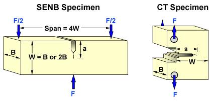
Figure 1: Examples of common fracture toughness test specimen models.
When carrying out these tests additional controls are also needed to ensure temperature control (e.g. use of an environmental chamber). SENB specimens are typically immersed in a bath for low temperature tests. If limited material is available, it is possible to fabricate SENB specimens by welding extension pieces (for the loading arms) to the material sample.
Access Fracture Mechanics Properties of Thousands of Materials Now!
Total Materia Horizon includes a unique collection of fracture mechanics properties such as K1C, KC, crack growth and Paris law parameters, for thousands of metal alloys and heat treatments.
Get a FREE test account at Total Materia Horizon and join a community of over 500,000 users from more than 120 countries.