Fatigue Properties : Part One
Abstract
Fatigue cracking represents one of the primary damage mechanisms affecting structural components in engineering applications. This phenomenon occurs when materials are subjected to cyclic stresses below their ultimate tensile strength or yield stress, causing progressive structural damage over time. The fatigue life of a component encompasses two critical phases: crack initiation and crack propagation to critical size. Understanding fatigue mechanisms is essential for structural design, particularly in aerospace applications where damage tolerance analysis assumes pre-existing flaws. This article examines the three-stage fatigue failure process, stress application methods, and the microscopic mechanisms governing crack initiation through persistent slip bands and dislocation accumulation.
Introduction to Fatigue Cracking Mechanisms
Fatigue cracking stands as one of the most significant damage mechanisms threatening structural components across various engineering applications. This insidious form of material failure occurs when components experience cyclic stresses that remain below the ultimate tensile stress, and often even below the yield stress of the material. The term "fatigue" aptly describes how materials become "tired" and fail at stress levels significantly below their nominal strength.
The particularly dangerous nature of fatigue damage stems from the fact that original bulk design strengths are never exceeded during the process. Often, the only warning sign of impending catastrophic fracture is a tiny, barely visible crack. This characteristic makes fatigue analysis and prevention crucial for structural integrity and safety.
Understanding Material Fatigue in Engineering Context
In materials science, fatigue manifests as progressive and localized structural damage occurring when materials undergo cyclic loading conditions. The maximum stress values during these cycles remain less than the ultimate tensile stress limit and may fall below the yield stress limit of the material.
Fatigue develops when materials experience alternating stresses over extended periods. Common engineering applications where fatigue concerns arise include springs subjected to repeated compression and extension, turbine blades experiencing rotational stresses, airplane wings enduring flight loads, bridge structures handling traffic loads, and even biological structures like bones under repetitive loading.
Stress Application Methods and Fatigue Cycles
Engineers recognize three primary methods for applying stresses that can lead to fatigue: axial, torsional, and flexural loading.
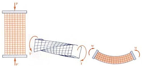
Figure 1: Visual examples of axial stress, torsional stress, and flexural stress
These stress application methods correspond to different loading scenarios encountered in real-world applications.
Types of Stress Cycles
The loading patterns that cause fatigue can be categorized into three distinct stress cycles. The simplest pattern is the reversed stress cycle, which follows a sine wave pattern where maximum and minimum stresses are equal in magnitude but opposite in sign. Rotating axles exemplify this type of loading, where every half rotation reverses the stress on any given point.
More commonly encountered in engineering applications is the repeated stress cycle, where maximum stress (σmax) and minimum stress (σmin) are asymmetric rather than equal and opposite. This asymmetric sine wave pattern represents the typical loading conditions found in most structural applications.
The third and most complex pattern involves randomly varying stress and frequency conditions. Automobile shock absorbers exemplify this loading type, where road surface irregularities create varying frequencies and magnitudes of stress cycles.
Fatigue Life and Design Considerations
The fatigue life of any component can be quantified as the total number of loading cycles required to initiate a fatigue crack and subsequently propagate that crack to its critical size. This definition encompasses the complete failure process from initial crack formation to final fracture.
Design considerations vary significantly depending on application requirements. For some components operating under high stress levels or having small critical flaw sizes, engineers may neglect the crack propagation phase in their calculations. Conversely, other components may derive substantial service life from the crack growth phase, making this stage a critical design consideration.
Pre-existing flaws or sharp design features can dramatically reduce or virtually eliminate the crack initiation portion of fatigue life. In such cases, the useful service life becomes governed primarily by subcritical crack propagation rates.
Aerospace Applications and Damage Tolerance
Aircraft fuselage structures provide excellent examples of designs based primarily on slow crack growth rate principles. Historical analysis by the United States Air Force of numerous malfunction reports across various aircraft types revealed that structural failures predominantly resulted from three sources: built-in preload stresses, inherent material flaws, and flaws developed during service usage.
These findings led to the development of damage tolerance analysis approaches that assume material flaws exist in the worst possible orientation and at the most critical locations. This conservative design philosophy ensures that structures can support slow, stable crack growth until cracks reach lengths detectable through non-destructive testing (NDT) methods.
Three-Stage Fatigue Failure Process
Fatigue failure occurs through a well-defined three-stage process: crack initiation, slow stable crack growth, and rapid fracture. Understanding each stage provides insight into failure mechanisms and potential intervention strategies.
Stage One: Crack Initiation
During the initial stage, dislocations play a fundamental role in crack initiation. These dislocations accumulate near surface stress concentrations and form specialized structures called persistent slip bands (PSB) after experiencing numerous loading cycles. PSBs manifest as surface irregularities where material movement along slip planes creates areas that rise above (extrusions) or fall below (intrusions) the component surface.
These surface discontinuities create tiny steps that function as stress concentrators, providing nucleation sites for microscopic cracks. These microcracks typically form along planes experiencing high shear stress, often oriented at approximately 45 degrees to the primary loading direction.
Stage Two: Crack Propagation
The second stage begins when some microcracks coalesce and start propagating through the material in directions perpendicular to maximum tensile stress. During this phase, one or several larger cracks typically dominate growth patterns while smaller cracks become less significant.
Continued cyclic loading drives the growth of dominant cracks until the remaining uncracked cross-section can no longer support the applied loads. This progression continues until the material's fracture toughness is exceeded.
Stage Three: Rapid Fracture
The final stage occurs when fracture toughness limits are exceeded, causing rapid overload fracture through the remaining material cross-section. This rapid failure represents the culmination of the progressive damage accumulation that characterizes fatigue failure.
Microscopic Analysis of Fatigue Failure
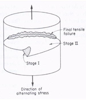
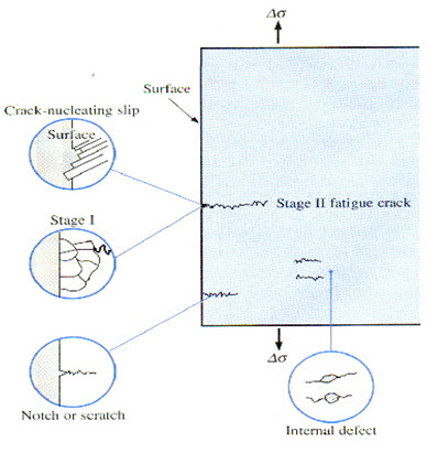
Figure 2A and 2B: A diagram showing location of the three steps in a fatigue fracture under axial stress
Material failure due to fatigue can be examined at the microscopic level through three distinct steps: crack initiation, crack propagation, and final failure. Understanding these microscopic processes proves essential since undetected cracks ultimately lead to material failure.
When materials experience cyclic tensile stress in the horizontal direction, crack initiation can result from several mechanisms. The primary causes include nucleating slip planes, stress concentrations at notches, and internal material flaws. Each mechanism contributes to the overall fatigue susceptibility of structural components.
Conclusion
Understanding fatigue properties remains fundamental to safe structural design across engineering disciplines. The progressive nature of fatigue damage, combined with its occurrence below nominal design stresses, makes this failure mechanism particularly challenging to predict and prevent. Through comprehensive analysis of stress application methods, failure stages, and microscopic mechanisms, engineers can develop more robust designs capable of withstanding the demanding cyclic loading conditions encountered in service.
Access Cyclic Properties of Thousands of Materials Now!
Total Materia Horizon includes a unique collection of fatigue properties of metallic and nonmetallic materials, for both low- and high cycle fatigue.
Get a FREE test account at Total Materia Horizon and join a community of over 500,000 users from more than 120 countries.