Application of Fracture Mechanics
Abstract
Fracture mechanics is a useful method of characterizing fracture toughness, fatigue crack growth, or stress-corrosion crack growth behavior in terms of structural design parameters familiar to the engineer, namely stress and flaw size.
The fracture mechanics can be used in three major areas: (i) design; (ii) material selection and alloy development; and (iii) determining the significance of defects.
Fracture mechanics is a useful method of characterizing fracture toughness, fatigue crack growth, or stress-corrosion crack growth behavior in terms of structural design parameters familiar to the engineer, namely stress and flaw size. Fracture mechanics is based on a stress analysis and does not depend on the use of service experience to translate laboratory results into practical design information (as with the Charpy V-notch test, for example).
Fracture mechanics can be used in three major areas: (i) design; (ii) material selection and alloy development; and (iii) determining the significance of defects. Ancillary areas are (iv) monitoring and control, and failure analysis. Each of these areas will be expanded upon throughout this article.
Conventional design procedures are based upon the yield strength or ultimate tensile strength. This approach was considered to be relatively safe when appropriate safety factors were used. Instances where unstable fracture occurred at stresses below the yield stress however necessitated making provision for such circumstances. Fracture mechanics provides this alternative in terms of the KIC value, but cyclic stressing and fatigue crack growth rate also have to be taken into account.
Factors of safety can then be used on the initial defect size, the working stress, and/or the anticipated number of loading cycles. An example of the practical application to design may be given in the main structural framework. Another example is the design against brittle fracture of a main coolant pump in a nuclear reactor primary circuit. The housing was constructed from three C-1/2%Mo steel castings which were welded together to form a casing having wall thickness from 4 in. to 22 in. and weighing about 32 tons, after internal surfaces had been clad with stainless steel. Because of the high toughness of the steel, an LEFM approach was not valid and COD and J-integral tests were carried out over a range of temperatures (-50 to +70°C) (-58 to +158°F).
A good correlation between these parameters was found. The finite element method was used to determine the stress fields for proof test loading and three service conditions, start, running and stop. The analysis carried out provided valuable information for design engineers, on the stress distribution and critical defect sizes in the castings. Charpy V-notch and drop-weight tests were also made and will be used in the future for quality control purposes.
Since the 1940’s, the problem of brittle fracture has been extensively studied. It has been found that with such low-stress (compared to the yield stress of the material) fractures always originate at flaws or cracks of various types. The fracture-mechanics approach to residual static strength in the presence of a crack makes use of the stress intensity factor KI concept to describe the stress field at a crack tip; when KI reaches a critical value KC the crack extends, usually catastrophically. Values of KI are known for a wide range of crack configurations, and the fracture-mechanics approach has proved useful in problems of material development, design, and failure analysis. In view of its success in dealing with static fracture problems, it is logical to use a similar general approach to analyze fatigue crack growth data.
In the mid 20th century, many researchers stated how early in the fatigue life they could observe micro cracks. Since then it has been clear that the fatigue life under cyclic loading consists of two phases: the crack initiation life, followed by the crack growth period until failure. This can be demonstrated in a block diagram, see Figure 1. The crack initiation period may cover a large percentage of the fatigue life under high-cycle fatigue, i.e. under stress amplitudes just above the fatigue limit. However, for larger stress amplitudes the crack growth period can be a substantial part of the fatigue life.
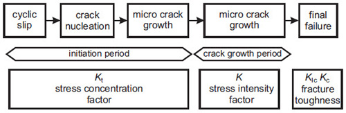
Figure 1: Various periods of fatigue life and applicable considerations
For the range of the elastic stress intensity factor, ΔK, alternative parameters were developed to correlate crack propagation rates under conditions of elastoplastic crack growth, as follows: (i) crack tip plastic range, (ii) change in crack tip opening displacement, and (iii) cyclic J-integral.
As early as the 1960s it was known that the correlation of da/dN and ΔK depends on the stress ratio R. This was to be expected, because an increased mean stress for constant loading ΔS should give faster crack growth while the R-value is also increased. Furthermore, the results of crack growth tests indicated systematic deviations of the Paris equation at relatively high and low ΔK values.
This led to the definition of three regions in da/dN-ΔK diagrams, namely zones I, II, and III, see Figure 2. Evident questions are connected with the vertical asymptotes at the lower ΔK boundary of zone I and the upper ΔK boundary of zone III. The latter boundary seems to be reasoned, since if Kmax exceeds the fracture toughness (either KC or KIC), a quasi-static failure will occur and fatigue crack growth is no longer feasible. Further, it should be identified that the Kmax value causing specimen failure in the last cycle of a fatigue crack growth test may well very from KC or KIC measured in a fracture toughness experiment.
From the standpoint of fracture mechanics, the incidence of a lower boundary in region I is not so obvious. If a K-value can be defined for the tip of a crack, a singular stress field should be on the scene and micro-plasticity at the tip of the crack should abound. Thus, why should the crack not propagate any more; for which physical reason should there be a threshold ΔK-value (ΔKth). New inspirations on ΔKth were connected with observations on so-called small cracks. These cracks occur as micro-cracks at the beginning of the fatigue life starting at the material surface or, more exactly, in the subsurface.
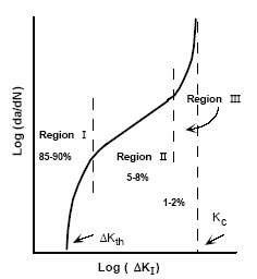
Figure 2: Typical Crack Growth Rate vs. Stress Intensity Range
An example of the practical application to design may be given in the main structural framework of the Beaubourg Centre, Paris, France. The design of the Beaubourg Centre was the subject of an international architectural competition, launched in 1971. Of the 681 schemes submitted, the winning architects were Piano and Rogers, and the winning engineering design was that of Ove Arup and Partners. The latter were inspired to use steel castings in their design following a visit to Japan, where they saw spherical cast steel nodes in the three dimensional structures at "Osaka 1970" which possessed a clean simplicity rarely found elsewhere.
The Beaubourg building has six floors and is divided lengthwise into 13 bays, each measuring 12.8 x 48 m (42 x 157.5 ft.) and are uninterrupted by internal load-carrying columns. Because cast steel was a new material to the design engineers, it was necessary to devise, in collaboration with the constructional engineers, new methods for testing and inspection. Ultrasonic testing of the nodes for the main girders is shown in progress in the production stage. It was appreciated that some defects were inevitable in cast and welded components and that non-destructive tests could not be relied upon to reveal every shortcoming.
The fracture toughness tests showed the cast steel exhibited the required standards of quality. After preliminary welding tests had indicated the correct welding procedures, ultimate tests to collapse proved that it was possible to attain satisfactory and, in some cases, excellent results.
Another example is the design against brittle fracture of a main coolant pump in a nuclear reactor primary circuit. The housing was constructed from three C-1/2%Mo steel castings which were welded together to form a casing having a wall thickness from 4 in. to 22 in. and weighing about 32 tons, after internal surfaces had been clad with stainless steel.
Access Fracture Mechanics Properties of Thousands of Materials Now!
Total Materia Horizon includes a unique collection of fracture mechanics properties such as K1C, KC, crack growth and Paris law parameters, for thousands of metal alloys and heat treatments.
Get a FREE test account at Total Materia Horizon and join a community of over 500,000 users from more than 120 countries.