Increasing the Efficiency on ERW/HFI Tube Mills: Part One
by Pierre Huot, Vice President, Xiris Automation Inc.
Abstract
Electric resistance welding (ERW) has, for many years, been used for making longitudinal seam welds in steel line pipe, principally for use in low grade structural and water pipeline applications. The advent of high frequency induction (HFI) techniques has led to significant improvements in weld quality which, in combination with greater control of the raw material chemical composition, has led to the production of high quality line pipe suitable for more stringent applications such as oil and gas pipelines.
Introduction by Key to Metals
Electric resistance welding (ERW) has, for many years, been used for making longitudinal seam welds in steel line pipe, principally for use in low grade structural and water pipeline applications. The advent of high frequency induction (HFI) techniques has led to significant improvements in weld quality which, in combination with greater control of the raw material chemical composition, has led to the production of high quality line pipe suitable for more stringent applications such as oil and gas pipelines.
Although this product form has been successfully used for many years in Canada for sour service environments, and is used in the North Sea for sweet and some sour applications, there is still some resistance to the use of ERW/HFI line pipe by some operators particularly for sour service applications. This lack of confidence appears to be based on historical problems related principally to pressure reversals and preferential weld line corrosion, even though these problems have been overcome.
The quality which can be achieved in modern ERW/HFI line pipe has improved dramatically with improvements in strip quality and greater understanding of the welding process and non-destructive testing technology. It offers closer dimensional control, which is of great value in pipelaying, and potentially significant cost savings over seamless pipe for similar applications.
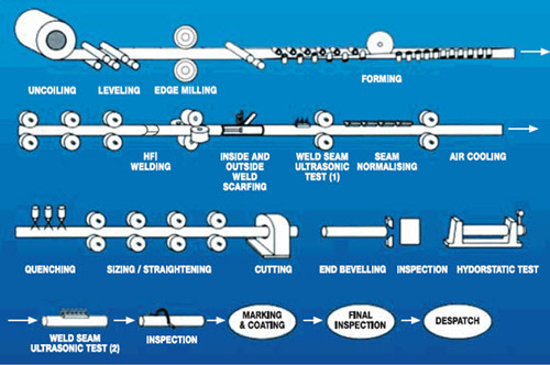
Figure 1: ERW manufacturing process
ERW / HFI tube fabrication is the fastest methods to produce tube product and the industry is one of the most competitive environments where high volume does not necessarily equate to profit.
How Manufacturers Can Improve Their Process Yield
The process of welding tube and pipe requires several variables to be in check for efficient stable production. The material type, gauge, edge condition, tooling setup, and weld heat are just a few of the factors that quality control managers, mill supervisors, and operators must pay attention to in their efforts to achieve output and efficiency targets.
In addition to controlling variables to maximize yield and optimize efficiency, they also must meet the quality demands of the market. Mill dynamics, from setup to production, ultimately impact profitability, competitiveness and the reputation of industry players. Optical tube measurement during setup and production offers gains in efficiency and yield with a goal to reduce scrap and waste by 25%.
This paper will present the challenges facing tube fabricators which impede mill efficiency and profitability and introduce the advantages of optically measuring the infeed tube forming parameters for setup and production as an early warning indicator for potential mill and material problems.
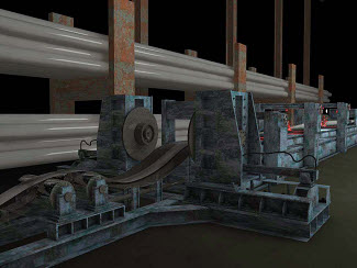
Figure 2: Tube mill
Market Trends
In an industry where the supply & demand curve can swing a firm from profit to loss within a fiscal year, tube fabricators face continual pressure from supplier side steel prices, competitor side capacity and buyer side quality demands. The environmental pressure from national and offshore competition, energy availability and conservation impact the profit dynamic as well.
By its nature, the tube and pipe industry has always been fragmented, chaotic and unpredictable. The market forces that shape it, have also forced the survivors to redefine it. The industry has undergone mill maneuvers as firms with heavy coffers acquired or consolidated with complimentary or competing fabricators. Companies have also closed plants to relocate their assets to lower cost based countries.
With the jostling taking place, experienced mill operators may have been lost in the shuffle thereby shrinking the experience pool. In mature markets the remaining players are in expansion. In the emerging markets, new fabricators are coming online annually which is increasing the regions prominence for tube fabrication on the world stage.
In the classic context of market forces producers have little bargaining power and therefore need to look to technology to minimize risk.
The Challenges Facing Tube Fabricators
Tube mill operators, mill supervisors and quality managers face a variety of daily challenges that impede their efforts to produce high quality tube product. As the old adage goes “garbage in, garbage out” and the same thing applies to tube fabricators.
A common condition which impacts the sizing and wall thickness after scarfing is the strip edges entering the welding area in non parallel fashion. This produces a step, mismatch, which then causes irregular sizing downstream through the sizing area.
While it is difficult to root out the main cause, the two most probable causes are improper setup in the breakdown, forming and fin section to ensure proper presentation to the welding section and strip rolling in the breakdown section which may cause the strip to ride high on one side. The strip edge riding high on one side can also be caused by negative tension in the tube mill. The back pressure causes the material to buckle and since the energy needs to be released the material follows the path of least resistance, up the side of a forming roller.
It is worthwhile to note that there can be two kinds of edge misalignment which leads to defects. The first one mentioned in the previous paragraph is a trending error and the second one is an intermittent error which is a wrinkle in the strip material over a short distance. This second disturbance can be the result of misaligned breakdown passes, improper edge preparation or possibly a raw material supplier quality issue.
Lost Runtime from Setup
The mechanical error due to the mill in poor condition, mill misalignment or tooling in poor condition impacts the production line yield. If we assume that this is not the case, there are setup steps that impact the changeover time and add to the waste stream:
- During setup, sections are cut from the mill to check for weld integrity. The mill then has to be rethreaded and repeated if the check fails. The iterative process is time consuming and contributes to reduced efficiency and material waste.
- Obtaining the correct Apex angle as part of the setup involves running material through the mill before the apex angle is properly set which also contributes to reduced efficiency and material waste.
- At setup, the last fin pass roller and the squeeze rollers in the weld box need to be bottomed out and in alignment.
- At setup if the alignment is not done properly, the sizing section may not develop enough positive tension, especially during reshaping, the tension before the weld roll can be negative, which is harmful to edge presentation and to welding.
The Importance of the Vee
If asked what the Vee angle should be for a given tube size and material, many are not sure what that value should be. However knowing where V angle should be and the gap values along the V leading to the apex can make a difference in boosting efficiency. What happens in the Vee is all important.
Everything that happens there can affect weld quality and speed. High frequency current density is highest in the edges near the apex of the V and at the apex itself. Encouraging high frequency current flow in the Vee depends on the Vee dimensions and the angle of opening.
Two conditions must be present to obtain the best electrical conditions for the weld:
- A maximum portion of the total high frequency current should flow in the Vee.
- The edges must be parallel in the Vee so that the heating of the seam will be uniform.
With parallel edges the oxides and other impurities are squeezed out in both directions. In general terms a Vee angle of 2-7 degrees is desirable for carbon steel. In process this angle could oscillate thereby changing the position of the apex point with respect to the weld pressure centerline. The oscillation could be due improper setup, worn forming rollers or material spring back which implicates the raw material supplier if this is undesirable.
Find Instantly Thousands of Welding Materials!
Total Materia Horizon contains thousands of materials suitable for welding and electrodes, with their properties in bulk and as welded conditions.
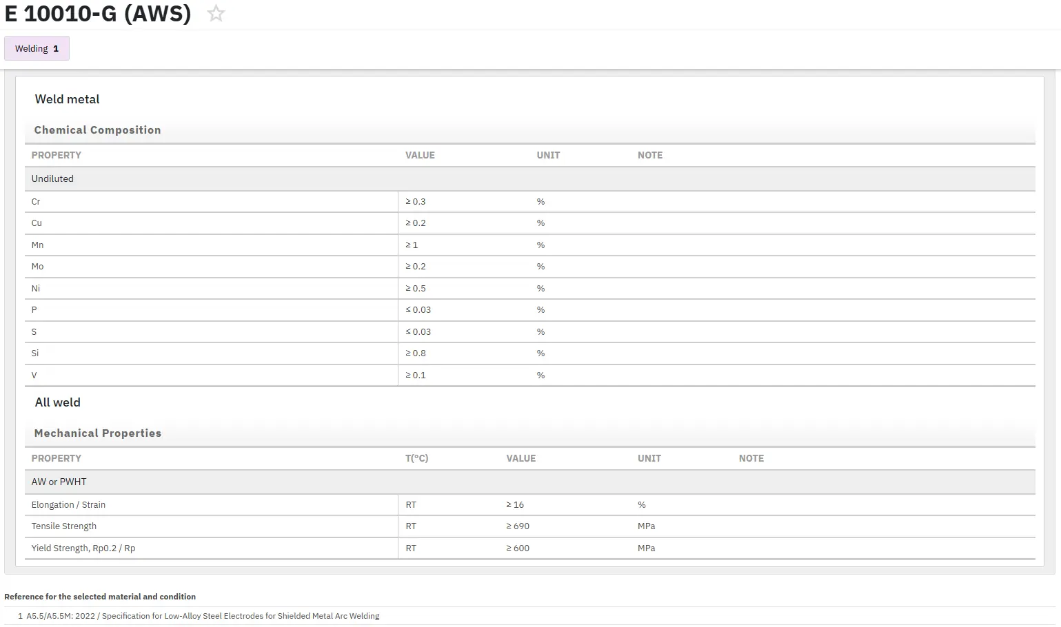
Get a FREE test account at Total Materia Horizon and join a community of over 500,000 users from more than 120 countries.