Rail Steels: Part Two
Abstract
Grade 700 rails that used to be the main product for railroads some 60 years ago, may be considered as the starting point for the development which since took place. The Grade 700, with about 0.5% C, has a microstructure of about 30% ferrite and 70% pearlite within the rail head, which is the relevant location for comparison.
The first step to raise strength, and consequently wear resistance, was to increase the carbon content to achieve a 100% pearlitic microstructure. This way Grade 900 rails were developed.
Microstructures and Properties of Pearlitic Rail Steels
Pearlite is an important feature of the microstructure because it possesses good wear resistance, hence making carbon an essential alloying element in rail steels. However, it is not only the amount of pearlite that is important but also its morphology, which means the shape and the distance between the cementite lamellae. The finer the structure of pearlite, the higher is its strength whilst still retaining reasonable toughness. Therefore the development of pearlitic rail steels has been focused on the refinement of pearlite.
Pearlite comprises a mixture of relatively soft ferrite and a hard, brittle iron carbide called cementite, taking the form of roughly parallel plates. It achieves a good resistance to wear because of the hard carbide and some degree of toughness as a result of the ferrite's ability to flow in an elastic/plastic manner. Figure 1 shows the microstructure of a pearlitic rail steel. The cementite is white and the ferrite is black. The interlamellar spacing is about 0.3 microns.
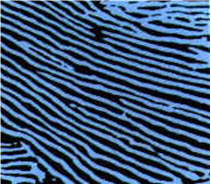
Figure 1: Microstructures of pearlitic rail steels.
Grade 700 rails that used to be the main product for railroads some 60 years ago, may be considered as the starting point for the development which since took place. The Grade 700, with about 0.5% C, has a microstructure of about 30% ferrite and 70% pearlite within the rail head, which is the relevant location for comparison.
Due to the rather slow cooling of the rail head on the cooling bed after rolling, the pearlite structure is relatively coarse. The first step to raise strength, and consequently wear resistance, was to increase the carbon content to achieve a 100% pearlitic microstructure. This way Grade 900 rails were developed.
The wear resistant rails of Grade 900 have a coarse pearlitic microstructure with sufficient ductility and toughness for general applications. Welding techniques were developed to replace fishplate connections and Grade 900 became the standard rail instead of Grade 700 for main lines. Nowadays Grade 700 rails are only used for tracks where low axle loads are applied, e.g. for trams. In some places like narrow curves and mountainous regions, but mainly for heavy haul ore and coal transportation, strengths greater than that exhibited by Grade 900 rails are needed; an increase in tensile strength of about 200 MPa doubles the wear resistance of the rails and consequently their service life.
The further strengthening of pearlitic rails to 1100–1200 MPa tensile strength is based on increased pearlite refinement. As shown in Figure 2, the properties of rail steels are influenced by the spacing between cementite lamellae. The yield strength and tensile strength increase as the interlamellar spacing decreases while the elongation decreases with a reduction in the interlamellar spacing.
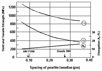
Figure 2: Effect of pearlite refinement on the properties of rail steel.
The continuous cooling transformation (CTT) diagram of Grade 900 steel shows two possibilities for achieving pearlite refinement. Firstly, as shown in Figure 3, the field of austenite to pearlite transformation may be moved to the right, e.g. through additions of chromium and other alloying elements, so that air cooling of the rail head transforms the austenite into fine pearlite with narrow interlamellar spacing. This type is the high strength and highly wear resistant alloy Grade 1100-1200, which cools at still air after rolling.
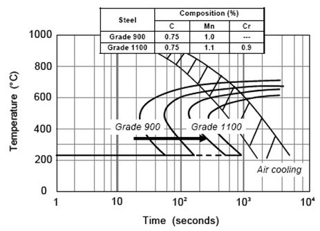
Figure 3: CCT diagram showing the effect of alloying to achieve pearlite refinement.
The second possibility is that the cooling speed of the rail head may be accelerated to move the austenite to pearlite transformation of the Grade 900 steel to the left in order to achieve a microstructure of fine pearlite; generating a 1100-1200MPa tensile strength with the same steel composition as shown in Figure 4.
This type is a head-hardened rail. The heat treatment and accelerated cooling (slack quenching) of the rail head may be performed after reheating (offline) or using the still austenitic microstructure directly after rolling (in-line).
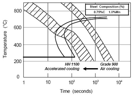
Figure 4: CCT diagram showing the effect of cooling rate on pearlite refinement.
The changes in pearlite transformation temperature in these two types of rails caused by changes in the cooling rate from the austenite region are schematically shown on the CCT diagram, Figure 5. To set the pearlite transformation temperature at about 600°C, slack quenching (cooling rate: 4-6°C/s) is required for the carbon steel rail, while natural air cooling (cooling rate: ~0.7°C/s) after hot rolling is sufficient for the alloy steel rail due to the high hardenability from alloying. These treatments could give the rails more than 1100MPa tensile strength.
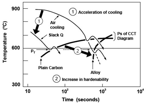
Figure 5: Pearlite transformation temperatures of high strength rails depending on cooling rate and alloying content.
Access Thousands of Stress-Strain Diagrams Now!
Total Materia Horizon includes a unique collection of stress-strain curves of metallic and nonmetallic materials. Both true and engineering stress curves are given, for various strain rates, heat treatments and working temperatures where applicable.
Get a FREE test account at Total Materia Horizon and join a community of over 500,000 users from more than 120 countries.