Cold Metal Transfer (CMT) Welding: Part Two
Abstract
Specifically aimed at the sheet metal industry, Cold Metal Transfer welding processes are a prospective set of methodologies where there is a deep requirement for control over welding distortions or deformations.
Traditionally a GMAW process, work on CMT technology has led to the possibility to apply these techniques to a conventional MIG/MAG processes meaning more possibilities to utilize its advantages as a cold welding technique.
The CMT (Cold Metal Transfer) process is a revolution in welding technology, with respect to both, welding equipment and welding applications. The CMT process is not only a completely new process, which is unknown until now, but it also opens a new field of application since it widens the limits of Gas Metal Arc Welding (GMAW), allowing the arc joining of steel to aluminium in a reproducible manner for the first time. There are materials and applications that cannot withstand the constant heat of a welding process. In order to avoid weld-pool drop-through, to be spatter-free, and to be amenable to metallurgical joining, they need lower temperatures. With CMT, this is now possible. The term “cold” has to be understood in terms of a welding process, but when set against the conventional MIG/MAG process, CMT is indeed a cold process.
As mentioned above, CMT can be described as a GMAW process where heat input is low as compared to the conventional dip arc process. The CMT-process is a dip arc process with a completely new method of the droplet detachment from the wire. In the conventional dip arc process the wire is moved forward until a short circuit occurs for welding happens (see Figure 1). At that moment, the welding current rises. Causing the short circuit to reopen and allowing the arc to ignite again. There are two main features of the MIG/MAG process: on the one hand the high short circuit current corresponds to a high heat input. On the other hands the short circuit opens in a rather uncontrolled manner, resulting in lots of spatters in the conventional dip arc process.
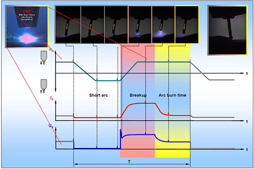
Figure 1: CMT arc sequence
Using the CMT method, 1mm thick DX54D+Z200 steel sheets were joined to 1.5mm thick AW5182-H111 sheets at Fronius International GmbH using 1.2mm diameter Al99.5 and AlSi3Mn1 filler wires, all parent materials being provided by Voest-Alpine Stahl GmbH. The optimized Voest-Alpine welding geometry (Figure 2) and optimized parameters for the CMT welding process were chosen (Table 1). The samples were clamped during the joining process in order to avoid distortion.
For optical (OM) and scanning electron (SEM) microscopy, specimens were cut, ground and polished until a specular surface was obtained. Specimen microstructure was characterized in the SEM using electron back scattering diffraction (EBSD).
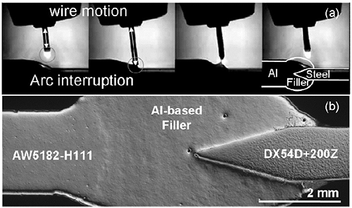
Figure 2: (a) Sequence of CMT process stages and b) Geometry of the steel-aluminum CMT joint (detail from (a), right)

Table 1: Welding parameters
Where is: vS: Welding speed, vD: Wire feeding speed, I: Current, U: Voltage, f: Frequency.
Residual stress analysis was carried out using the instrument G3 at HASYLAB, DESY, Hamburg, Germany at 6.4 keV energy. Residual stresses in longitudinal (along the weld) and in transversal direction were determined by the sin2Ψ method (Al311 and α-Fe200 reflections) at the top and bottom of a AW5182-H111 aluminum to DX54D+Z200 steel butt-joint with AlSi3Mn1 filler, in the center of the weld seam and along both the steel and aluminum sheets up to 80mm distance from the weld centerline (Figure 3). Face and bottom sides of the butt joint were electro-polished in order to access residual stresses in a depth of 100μm beneath the original surface. After electro-polishing residual stresses were determined in the weld seam, and in the aluminum and steel sheets up to a distance of 35mm from the weld seam. The diffraction elastic constants were calculated using Kröner’s model.
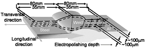
Figure 3: Scheme of stress measurement locations
Micrographs of the welded samples reveal different intermetallic phase morphologies (Figure 4) at the interface between the molten filler and the steel when using Al99.5 and AlSi3Mn1 filler materials. The chosen welding parameters ensured that the thickness of the intermetallic phase seam (IMP) in both welds with Al99.5 filler (IMP thickness about 3.5μm) and AlSi3Mn1 filler (IMP thickness about 2.5μm) was well below the 10μm limit, which often has been claimed to be critical with respect to weld toughness. The phases identified in the IMP of the weld with the Al99.5 filler are θ-phase Al3Fe (adjacent the filler) and η-phase Al5Fe2 (adjacent to the steel). The intermetallic phase seam in case of the AlSi3Mn1 filler contains also the θ-phase Al3Fe and the η-phase Al5Fe2 and additionally an Al(Fe,Mn)Si – phase.
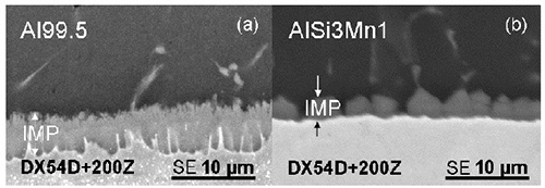
Figure 4: SE-SEM micrograph showing the intermetallic phase seam (IMP) in welds with (a) Al99.5 filler and (b) AlSi3Mn1 filler
The residual stress distribution in longitudinal direction both at the top (Figure 5a) and the bottom side of the weld (Figure 5b) are characterized by compressive residual stresses within the steel plate parent material, which turn into tensile residual stresses in the heat affected zone with a steep gradient. The filler in the weld seam and the heat affected zone in the aluminum alloy are under tensile residual stresses, and the aluminum parent material contains balancing compressive residual stresses in longitudinal direction. The maximum value of the residual stresses in the aluminum alloy, on the top side of the weld near the weld seam, is as high as 100 MPa and, thus, about 2/3 of its yield strength. The residual stress distribution in transversal direction at the bottom side of the weld (Figure 6) is very similar to the residual stress distribution in longitudinal direction. The residual stress values encountered are slightly lower in transversal direction compared to the longitudinal direction.
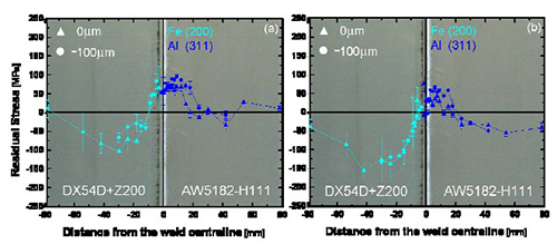
Figure 5: Residual stress state along the longitudinal direction (↓) of a joint with AlSi3Mn1 aluminum filler on the surface and ~100μm beneath on (a) top and (b) bottom side
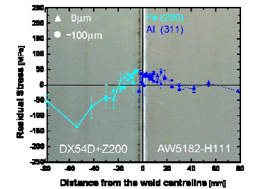
Figure 6: Residual stress state along the transversal direction (→) of a joint with AlSi3Mn1 aluminum filler on bottom side surface and ~100μm beneath it. [5] [4]
Find Instantly Thousands of Welding Materials!
Total Materia Horizon contains thousands of materials suitable for welding and electrodes, with their properties in bulk and as welded conditions.
Get a FREE test account at Total Materia Horizon and join a community of over 500,000 users from more than 120 countries.