Residual Welding Stresses
Abstract
Residual welding stresses significantly impact the service characteristics and potential failure of welded joints. This article examines three primary sources of these stresses: contraction during cooling, differential surface cooling rates, and phase transformation effects. Various measurement techniques are discussed, including X-ray diffraction, neutron diffraction, and numerical modeling approaches. Experimental results from neutron diffraction measurements on single-bead-on-plate welds demonstrate that peak stresses often exceed the specified yield stress of both parent and weld metals. Understanding these stresses is essential for preventing failures and optimizing welded structures across industrial engineering, shipbuilding, and pipeline fabrication.
Introduction to Welding Residual Stresses
Welding represents one of the most critical technological processes employed across numerous industries including industrial engineering, shipbuilding, and pipeline fabrication. Residual stresses that develop after welding significantly influence the service characteristics of welded equipment. Effective control of these stresses is essential to prevent failure of welded joints during service.
Various techniques are employed to control and analyze the stress state in weld regions. X-ray diffraction has become widely utilized for analyzing residual stress distribution in the weld seam and surrounding areas. However, measurements obtained through X-ray tensometry often contain contradictory information about weld-induced residual stresses. Additionally, stress distribution analysis frequently occurs without adequate consideration of equilibrium conditions.
Impact of Residual Stresses on Welded Structures
Tensile residual stresses can significantly reduce performance or directly cause failure of manufactured products. These stresses may accelerate damage through fatigue, creep, or environmental degradation processes. They can reduce load capacity by contributing to brittle fracture or cause other forms of damage including shape changes or crazing. While compressive residual stresses are generally beneficial, they can cause a decrease in buckling load capacity.
Measurement Techniques for Residual Stresses
Residual stress measurement techniques fall into several categories:
- Non-destructive techniques: Including X-ray diffraction, neutron diffraction, optical, magnetic, and ultrasonic methods
- Locally destructive techniques: Including hole drilling, ring core, and deep hole methods
- Sectioning methods: Including block removal, splitting, slicing, layering, and the contour method
Selecting the optimal measurement technique requires consideration of volumetric resolution, material properties, geometry, and access constraints.
Numerical modeling for predicting residual stresses in welding and other manufacturing processes has advanced rapidly in recent years. However, welding simulation remains technically and computationally demanding, necessitating simplification of material behavior, process parameters, and geometry. While numerical modeling provides a powerful tool for residual stress prediction, validation through experimental results remains essential.
Primary Sources of Residual Welding Stress
Residual stress in welds results from localized metal tensions occurring immediately after welding, which stem from three main sources:
- Contraction stress: The primary source of residual stress, occurring during cooling of welded areas that have undergone non-uniform heating.
- Stress due to higher surface cooling: When a weld cools, the surface cools faster than the interior, even in still air. The stress generation increases with material thickness.
- Stress due to phase transformation: This occurs during the transformation of austenite (face-centered cubic structure) to ferrite (body-centered cubic structure), causing a volume increase that the base metal resists.
Experimental Investigation Using Neutron Diffraction
A.M. Paradowsa and colleagues conducted experimental neutron diffraction measurements of weld stresses generated by single-bead-on-plate welds. Their study focused on line scans of stress (strain) variation through the middle of the weldment. The parent material was low-carbon steel. The chemical composition of the material and weld metal are shown in Table 1. The typical mechanical properties of parent and weld metal are shown in Table 2.
Table 1. Chemical composition of the consumable materials (in wt.%)
| Composition | C | Si | Mn | S | P | Ni | Cr | Mo | V | Al |
| Parent metal | 0.12 | 0.13 | 0.63 | 0.01 | 0.02 | 0.02 | 0.01 | 0.01 | <0.01 | 0.03 |
| Weld metal | 0.10 | 0.68 | 1.70 | 0.02 | 0.02 | 0.05 | 0.03 | 0.04 | 0.04 | - |
Table 2. Typical mechanical properties
| Mechanical Properties | Yield stress [MPa] | Tensile stress [MPa] | Elongation [%] |
| Parent metal | 285 | 429 | 38 |
| Weld metal | 445 | 550 | 29 |
Welding Procedure
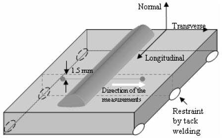
The experimental work utilized three specimens, all fully restrained single bead-on-plate welds. Restraint was achieved by tack welding each sample to a very thick steel plate, which was removed after cooling to room temperature.

Figure 1: Illustration of fully restrained single bead-on-plate, showing measurement directions using neutron diffraction
The welds were produced using a flux-cored arc welding (FCAW) process. The specimens were mounted under an automatic speed-controlled welding torch. The welding parameters are shown in Table 3. Table 4 shows the weld geometrical parameters. There was no pre- or post- weld heat (PWHT) treatment.
Table 3. Parameters used in the experimental work
| Sample | Heat input [kJ/mm] | Traverse speed [mm/mm] | Electrode diameter [mm] | Current range [A] | Voltage range [V] | Wire feeding speed [mm/min] | Electrode stick-out distance [mm] | Gas flow rate [l/min] |
| I | 0.8 | 560 | 1.6 | 260-280 | 28-30 | 3600 | 20 | 20 |
| II | 1.2 | 360 | 1.6 | 260-280 | 28-30 | 3600 | 20 | 20 |
| III | 1.6 | 280 | 1.6 | 260-280 | 28-30 | 3600 | 20 | 20 |
Table 4. Typical mechanical properties
| Sample | Heat input [kJ/mm] | Width [mm] | Height [mm] | Penetration [mm] |
| I | 0.8 | 560 | 3.0 | 2.0 |
| II | 1.2 | 360 | 3.5 | 2.5 |
| III | 1.6 | 280 | 4.5 | 3.0 |
Transverse sections were taken across the welds in the middle of each plate for all samples.
Results and Analysis
Residual stresses were derived from elastic strain measurements using a Young's modulus of 207 GPa and a Poisson's ratio of 0.3.

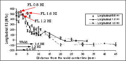
Figure 2: Longitudinal residual stresses measured by ND against distance from the weld center line

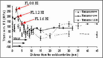
Figure 3: Transverse residual stresses
The peak stress in the longitudinal direction was significantly higher in the weld area across all samples compared to the specified yield stress of the parent metal (250 MPa). These stresses also exceeded the yield stresses of the weld metal. Importantly, significant hydrostatic tension (100–200 MPa) was observed in the fused zone, indicating that maximum principal stresses in the longitudinal direction can be higher than yield.
Notably, the peak stress did not occur under the toe of the weld but in the middle of the weld or at the fusion line. In the transverse direction, maximum residual stress of approximately half the maximum longitudinal stress value was observed at the fusion line, with decreasing values as heat input increased.
One possible explanation for these observations is the exceptionally high quench speeds associated with the fusion line, where liquid metal directly contacts the parent metal. Further research is developing methods to cross-check these results with finite element modeling of the welding process.
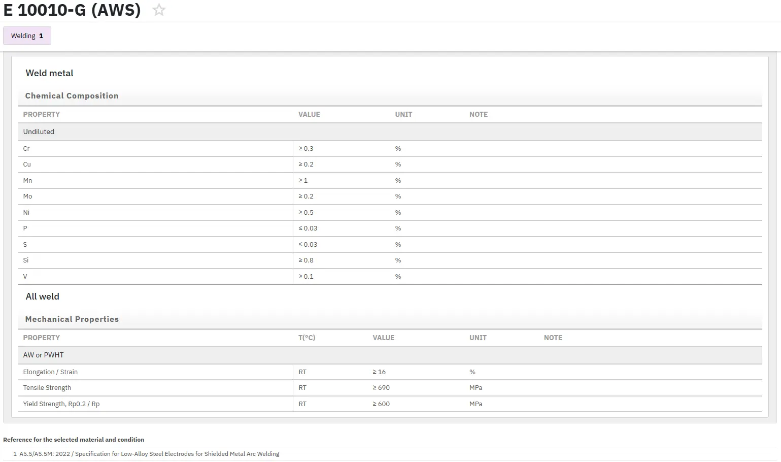
Find Instantly Thousands of Welding Materials!
Total Materia Horizon contains thousands of materials suitable for welding and electrodes, with their properties in bulk and as welded conditions.

Get a FREE test account at Total Materia Horizon and join a community of over 500,000 users from more than 120 countries.