Friction Stir Welding of Steel: Part Two
W.M. Thomas, P.L. Threadgill and E.D. Nickolas, TWI Ltd, Cambridge, United Kingdom
In this article, Friction Stir Welding trials which were carried out on a modified vertical heavy duty-milling machine are analyzed.
Unlike aluminum and most non-ferrous materials, which show little or no visible change during welding owing to increase in temperature, a color change was distinctive in the FSW of both grades of steel, which gave approximate indications of temperature. The tool shoulder reached a bright orange color which indicated an approximate temperature of over 1000°C, within a few seconds of making contact. Also as the tool travels along the seam, the ensuing weld track behind the trailing edge of the rotating tool appeared orange/bright red (900-1000°C).
2. EXPERIMENTAL
2.1 Friction Stir Welding Equipment
The Friction Stir Welding trials were carried out on a modified vertical heavy duty-milling machine. The machine frame is robust, avoiding any significant deflection during the FSW trials. Ample power for the steady rotation at 64 spindle speeds between 90 - 1400 rev/min is provided by two speed reversing motor that develops 22 kW at 1430 rev/min and 15 kW at 960 rev/min. The available traverse rate ranged between 0.5 mm and 15 mm/sec (0.03 and 0.9 m/min). A hydraulic force system, which had a maximum capability of 250 kN was also incorporated into the machine to provide the downward welding load.
Thermal imaging of selected welding trials was carried out using an Agema Thermovision 900 series infrared imaging system, with an accuracy of ±1°C or ±1% which ever is greater.
2.2 Materials
The workpiece material selected was 12 mm and 15 mm thick, low carbon steel grade BS970: Part 1 1983 07M0 (BS EN 10083-1) and 12 mm thick, 12 chromium alloy steel grade DIN 1.4003 (X2CrNi12), (EN 10083-1) with nominal compositions as follows:
Table 1: Chemical analysis of low carbon 12% chromium alloy parent steel (TWI analysis ref: S-98-153)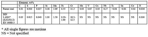
Table 2: Chemical analysis of low carbon 12% chromium alloy parent steel (TWI analysis ref: 9B-Rev6)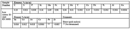
The tool geometry was substantially that of Whorl™ type as described elsewhere. Detailed weld parameters, dimensions of the tool material are still being further optimized. These initial feasibility studies however did achieve welding travel speeds of 1.7 to 4 mm/sec.
2.3 Welding Procedure
The steel workpiece plates were secured with work holding fixtures onto the machine traverse table. A pilot hole of smaller diameter than the probe was drilled between the abutting plates at the start of the weld seam. Touchdown conditions were set to minimize the stress on the tool. Traversing was the shoulder and probe. The friction stir welding operation was carried out at ambient temperature, with no auxiliary pre-heat or interpass heating of the workpiece being used. For double sided welds the first weld surface was dressed flat before turning the workpiece over and repeating the above procedure on the second weld pass.
2.4 Weld Assessment
All welds were visually examined for surface roughness, presence of surface breaking defects and side flash. A number of welds were tensile and bend tested, together with metallurgical examination. All sections were prepared in the direction looking towards the start of the weld and for clarity all macrographs are marked "advancing side" and "retreating side". Carbon steel sections were prepared to a 1μm finish and etched in nital. The 12% chromium alloy steel was etched in an ethanol solution containing 2.5% picric acid and 2.5% hydrochloric acid. Vickers hardness traverses, using a 10 kg indenting weight, were taken across a number of welds at both mid thickness and quarter thickness.
2.5 Microstructural Assessment of Friction Stir Welds
Studies of number of materials indicate that there are three primary microstructural regions to consider in friction stir welds, although these may be further sub-divided for certain materials. These regions are:
- 1. Unaffected parent material.
- 2. Material that has been affected by heat, but not mechanically deformed. This is defined as the heat affected zone (HAZ).
- 3. Material that has been affected by heat and mechanically deformed. This is defined as the thermo-mechanically affected zone (TMAZ)
The microstructures of the steels examined in this work can be categorized in this way.
3. RESULTS AND DISCUSSION
3.1 General Characteristics
Unlike aluminum and most non-ferrous materials, which show little or no visible change during welding owing to increase in temperature, a color change was distinctive in the FSW of both grades of steel, which gave approximate indications of temperature. The tool shoulder reached a bright orange color which indicated an approximate temperature of over 1000°C, within a few seconds of making contact. Also as the tool travels along the seam, the ensuing weld track behind the trailing edge of the rotating tool appeared orange/bright red (900-1000°C). This color changed to a darker cherry red (about 600°C) 25 mm from the tool. The tool shoulder maintained its bright orange color throughout a 1 meter length of weld.
For low carbon 12% chromium alloy steel thermal imaging measurements gave a maximum welding temperature close to the tool of around 1090°C. A typical temperature profile along the weld is shown in Figure 3. The temperature was also partly dependent on rotational speed increasing with high speed and falling with lower speed.
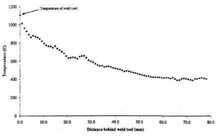
Figure 3: Temperature profile along the 12% chromium alloy steel weld, 250 mm of welding at a traverse rate of 3 mm/sec.
The surface of the steel welds showed, a uniform surface ripple (caused by the final sweep of the trailing edge of the rotating tool) which visually was not unlike that of a steel friction surfacing deposit, see for example Figure 4 for the hot work tool steel deposited on to carbon steel.
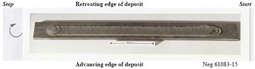
Figure 4: Typical friction surfaced deposit BS 4659 H13 (AISI H13, Werkstoff No 1.2344) hot-work tool steel deposited onto BS 970-1 080M40 (EN 10083-1) steel substrate.
However, unlike a deposit that clads the top of the workpiece the FSW weld appeared essentially flush with the surface as shown in figures 5&6. Apart from being a little coarser, the almost semicircular ripple in the weld track for steel was essentially the same as those for aluminum FSW welds. The closed part of the ripples are part of a continuous cycloidal motion that characterizes all friction stir welds.
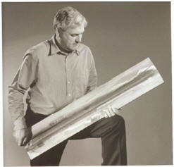
Figure 5: One meter long 12 mm thick 12% chromium alloy steel, double sided, test weld.
Transverse macrosections reveal HAZ profiles that correspond with the shoulder and probe geometry and reflect the degree of friction treatment received. Frictional contact at the shoulder produces a wide but relatively shallow HAZ which deepens in the centre region, and extends through-the-thickness to a depth and breadth governed by the probe. Typical overall HAZ profiles for double sided welds are shown in Figures 6, 7, and 8.
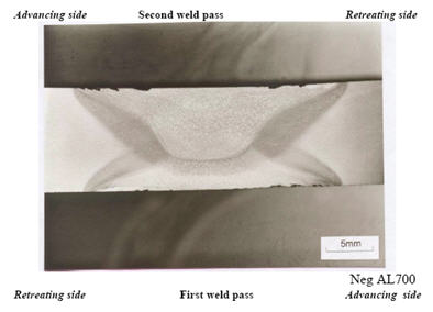
Figure 6: Macrosection of 12 mm thick doubled sided 12% chromium alloy steel FSW joint.
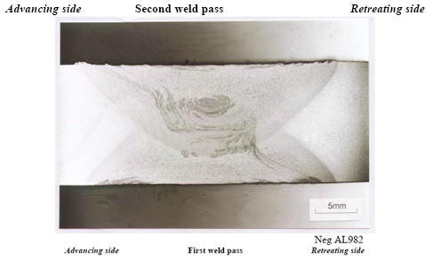
Figure 7: macrosection of 15 mm thick low carbon steel double sided test weld.
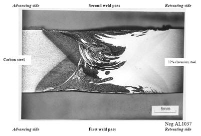
Figure 8: Transverse macrosection of dissimilar 12% chromium alloy steel/low carbon steel FSW double sided weld. (First pass hand ground flat).
A marked difference was found in the welding speed possible for the two types of steel. Acceptable welds could be produced at up to 4 mm/sec traverse rate for 12% chromium steel, but only at a slower 1.7 mm/sec traverse rate in carbon steel.
The dissimilar 12% chromium/carbon steel weld specimens differed from normal in that certain regions of the weld profile protruded above the plate surface. Some undercut was noticeable but essentially the surface appearance was marked with a shallow bulge 0.6 mm above the plate, which ran along the entire length of the weld. This bulge lay on the retreating side and mainly comprised of the 12% chromium material that came from the original plate of the joint as shown in figure 9.
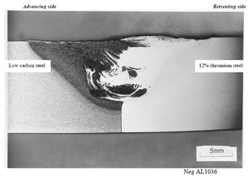
Figure 9: Transverse macrosection of dissimilar 12% chromium alloy steel/carbon steel. First weld pass showing increased hydrostatic effect with 12% chromium alloy shallow ridge above the plate surface.
The cyclic nature of the rotary friction stir welding process is revealed in detail in the macrophotograph (Figure 10) of a 20° tapered transverse section. This confirms that the cyclic pattern is consistent longitudinally and through-the-thickness and also shows that both the 12% chromium and the carbon steel have been moved across the original abutting plate interface.
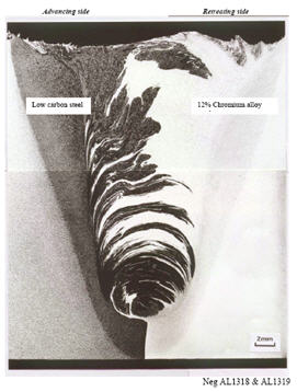
Figure 10: Transverse taper macrosection of dissimilar 12% chromium/low carbon steel FSW.