Structure of plain steel
Abstract
The essential difference between ordinary steel and pure iron is the amount of carbon in the former, which reduces the ductility but increases the strength and the susceptibility to hardening when rapidly cooled from elevated temperatures. On account of the various micro-structures which may be obtained by different heat-treatments, it is necessary to emphasise the fact that the following structures are for "normal" steels, i.e. slowly cooled from 760-900°C depending on the carbon contents.
The essential difference between ordinary steel and pure iron is the amount of carbon in the former, which reduces the ductility but increases the strength and the susceptibility to hardening when rapidly cooled from elevated temperatures. On account of the various micro-structures which may be obtained by different heat-treatments, it is necessary to emphasise the fact that the following structures are for "normal" steels, i.e. slowly cooled from 760-900°C depending on the carbon contents.
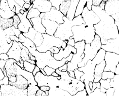
The appearance of pure iron is illustrated in Fig. 1. It is only pure in the sense that it contains no carbon, but contains very small quantities of impurities such as phosphorus, silicon, manganese, oxygen, nitrogen, dissolved in the solid metal. In other words, the structure is typical of pure metals and solid solutions in the annealed condition. It is built up of a number of crystals of the same composition, given the name ferrite in metallography (Brinell hardness 80).
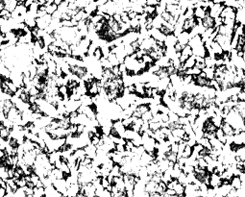
The addition of carbon to the pure iron results in a considerable difference in the structure (Fig. 2), which now consists of two constituents, the white one being the ferrite, and the dark parts representing the constituent containing the carbon, the amount of which is therefore an index of the quantity of carbon in the steel. Carbon is present as a compound of iron and carbon (6-67 %) called cementite, having the chemical formula Fe3 C. This cementite is hard (Brinell hardness 600 +), brittle and brilliantly white.
|
|  |
| x200 | x200 |
| Figure 1. | Figure 2. |
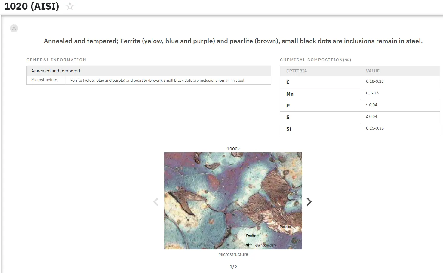
On examination the dark parts will be seen to consist of two components occurring as wavy or parallel plates alternately dark and light (Fig. 3). These two phases are ferrite and cementite which form a eutectic mixture, containing 0,87% carbon and known as pearlite. The appearance of this pearlite depends largely upon the objective employed in the examination and also on the rate of cooling from the elevated temperature.
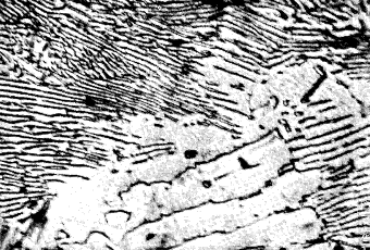 |
| Figure 3. |
Allotropy of iron
Certain substances can exist in two or more crystalline forms; for example charcoal, graphite and diamonds are allotropic modifications of carbon. Allotropy is characterized by a change in atomic structure which occurs at a definite transformation temperature.
Four changes occur in iron, which give rise to forms known as alpha, beta, gamma and delta. Of these, a, b and d forms have the same atomic structure (body centred cubic) while g -iron has a face centred cubic structure. Iron can, therefore, be considered to have two allotropic modifications.
The A2 change at 769°C, at which the a-iron loses its magnetism, can be ignored from a heat-treatment point of view. These changes in structure are accompanied by thermal changes, together with discontinuities in other physical properties such as electrical, thermo-electric potential, magnetic, expansion and tenacity. The A3 change from a b.c.c. to an f.c.c. atomic structure at 937°C is accompanied by a marked contraction while the reverse occurs at 1400°C. These changes in structure are accompanied by recrystallisation, followed by grain growth.
Critical points
The addition of carbon to iron, however, produces another change at 695°C, known as A1 and associated with the formation of pearlite. These structural changes, which occur during cooling, give rise to evolutions of heat, which cause arrests on a cooling curve. The temperatures of these arrests are known as critical points or "A" points. These arrests occur at slightly higher temperatures on heating, as compared with cooling, and this lag effect, increased by rapid cooling, is known as thermal hysteresis.
To differentiate between the arrests obtained during heating and cooling, the letters c and r respectively are added to the symbol A (from chauffage and refroidissement). In a steel containing about 0,8-0,9% carbon the evolution of the heat at Ar1 is sufficient to cause the material to become visibly hotter and the phenomenon is called "recalescence".
Iron-cementite equilibrium diagram
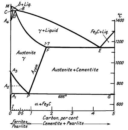
The addition of carbon to iron not only gives rise to the A1 point but also influences the critical points in pure iron. The A4 point is raised; and the A3 point lowered until it coincides with A1. The a, b and d modifications, which may be called ferrite, have only slight solubility for carbon, but up to 1,7% of carbon dissolves in y-iron to form a solid solution called Austenite. These effects are summarised in the iron-Fe3 C equilibrium diagram (Fig. 4), which is of much importance in the study of steels.
The iron-iron carbide system is not in true equilibrium, the stable system is iron-graphite, but special conditions are necessary to nucleate graphite. Will be seen that the complicated Fe-Fe3C diagram can be divided into several simple diagrams:
Peritectic transformation CDB - d-iron transforms to austenite. Eutectic at E - austenite and cementite. Solid solution D to F - primary dendrites of austenite form. Eutectic point at P - formation of pearlite.
|
|
| Figure 4. |
The ferrite solubility line, A3P, denotes the commencement of precipitation of ferrite from austenite. The cementite solubility line, FP, indicates the primary deposition of cementite from austenite. The pearlite line, A1PG, indicates the formation of the eutectic at a constant temperature. Let us consider the freezing of alloys of various carbon contents.
0,3% carbon
Dendrites of d-iron form, the composition of which is represented eventually by C (0,07 %), and the liquid, enriched in carbon, by B. The solid crystals then react with the liquid to form austenite of composition D. Diffusion of carbon occurs as the solid alloy cools to line A3P. Here a-ferrite commences to be ejected from the austenite, consequently the remaining solid solution is enriched in carbon, until point P is reached at which cementite can be also precipitated.
The alternate formation of ferrite and cementite at 695°C gives rise to pearlite. The structure finally consists of masses of pearlite embedded in the ferrite.
0,6% carbon
When line BE is reached dendrites of austenite form, and finally the alloy completely freezes as a cored solid solution, which, on cooling through the critical range (750-695°C), decomposes into ferrite and pearlite.
1,4% carbon
Again, the alloy solidifies as a cored solid solution, but on reaching line FP, cementite starts to be ejected and the residual alloy becomes increasingly poorer in carbon until point P is reached, when both cementite and ferrite form in juxtaposition. The structure now consists of free cementite and pearlite.
Find Instantly Thousands of Metallography Diagrams!
Total Materia Horizon contains a unique collection of metallography images across a large range of metallic alloys, countries, standards and heat treatments.
Get a FREE test account at Total Materia Horizon and join a community of over 500,000 users from more than 120 countries.
