Nondestructive Testing: Endoscopy
Abstract
Welding, which is one of the newer metalworking trades, can trace its historic development back to ancient times.
The earliest example comes from the Bronze Age. Small gold circular boxes were made apparently by pressure welding lap joints together. It is estimated that these boxes were made more than 2,000 years ago and are presently on exhibit at the National Museum in Dublin, Ireland.
An endoscope is an optical instrument which is used for visual inspection of interior surfaces in tubes, holes or other hard-to-reach places.
Endoscopes can be grouped into two main categories, namely the stiff borescopes and the flexible fiberscopes. It should be noted that other terms may be used for endoscopes, such as intrascope, motoscope, technoscope, and autoscope.
Stiff borescopes
The stiff borescopes can be compared to a periscope, where the objective is placed quite near the object or detail to be examined, while the ocular is placed at the desired distance from the objective.The objective and the ocular are connected by means of one or more removable extension tubes. The borescopic’s length can thus be varied as required. The image is transferred from the objective to the ocular by means of an optical system which is built into the tube.
The illumination of the surface to be observed is achieved by means of a 6-15 V halogen lamp of from 20-150 W which is contained in the objective lube. In short boroscopes the light may also be transferred by means of a bundle of optical fibers which thus serve as a light guide. The light guide surrounds the lens system itself and is in principle equivalent to trust of the fiberscopes.
The above-mentioned short borescopes cannot be extended and must therefore be ordered with the desired length. They are available in diameters in the range 1.7-18 mm and in lengths in the range 50-3500 mm.
Flexible fiberscopes
Flexible fiberscopes can, in contrast to the stiff borescopes, be inserted into curved pipes and cavities. The light in the fiberscopes is transmitted via ultrathin optical fibers with a diameter as small as 0.007mm.A fiberscope contains up to 120,000 fibers, each consisting of two layers of glass, namely a core of glass surrounded by an outer layer of glass of differing refractive index. When the light strikes the interface between the core material and the outer layer, a nearly perfect internal reflection occurs. In this way the light is guided through each individual fiber.
The fibers are separated into two bundles, one for transmitting light, the other for transmitting the image. The optical fibers are placed like a cloak outermost, and their function is to transmit the light from a cold light generator to the object which is to be perceived through the fiberscope. It terminates in one or more "projectors" surrounding the objective so that the object can be seen without awkward shadows.
The individual threads of glass are not well-ordered, for their mission is exclusively the transmission of light to the object. The image-forming bundle on the other hand is well-ordered. Thus every one of the 120,000 threads of glass has exactly the same relative position in both ends, i.e. both at the objective and at the ocular. The image is thus composed of 120,000 points of light (pixels) just like the image on a video monitor.
Both borescopes and fiberscopes can be supplied with distance adjustments just like an ordinary camera, so that the image can be focused sharply at any distance from a few millimetres up to infinity. When adjusting to very small distances the image is magnified, so that even very small details can be inspected.
The flexible fiberscope can be supplied in diameters ranging from about 1.7 to 13.5 mm and in lengths from about 300 to 6000 mm.
Video endoscope
The video endoscope represents a further development of the borescopes and fiberscopes discussed previous. Video endoscope equipment operates on the principle that a small electronic sensor detects the image and transmits the signals recorded to a video processor from which the signal is sent to a monitor. The electronic sensor is placed at the end of a flexible fiber optics cable. The cable can be obtained in lengths up to 30 meters and with a diameter down to 6 mm.In addition to providing a large, sharp color image -- the equipment is capable of automatic focus -- it is possible to type in a text in the image field, e.g. to indicate the location of the examination, the object, to freeze the image so that details can be studied, and more.
Development of the method
Visual inspection is perhaps the oldest form of non-destructive examination. It is still one of the most important. A wealth of data is acquired with a visual inspection including information about the condition of the surface, the form, color, occurrence of defects, etc. The use of endoscopes compensates for the inability of the eye to see around corners and for the limited resolution of the eye.The first endoscopes were developed for medical purposes and made it possible to see inside hollow organs or cavities from outside the body. Based on these first steps in the development process, technical instruments called boroscopes were derived. These borescopes are and were stiff instruments provided with lens optics and miniature incandescent lamp for illumination.
In the next generation the incandescent lamp was replaced by optical fiber illumination. In this manner the degree of illumination could be increased significantly thus allowing better photographic documentation.
A decisive stage of development was achieved with the const ruction of flexible glass fiber optics. In this manner it became possible to carry out inspections of very inaccessible surfaces, even those not accessible in a straight line.
As an alternative to the transmission of images via optical fibers as in the fiberscope, the image can now be acquired by means of a small electronic sensor which transmits the signals to a video processor and then to a monitor. This means that it is possible to use much longer cables with the endoscope than was previously possible.
Areas of application Endoscopes can be used for a wide range of applications. If internal visual inspection of pipes, boilers, cylinders, motors, reactors, heat exchangers, turbines, and other products with narrow, inaccessible cavities and/or channels is to be performed, then the endoscope is an important, if not an indispensable instrument.
Many jobs make special demands upon the endoscopy equipment. A glance at a few equipment catalogues shows a wide assortment of both traditional as well as more specialized equipment, of which the following will be described briefly here:
Find Instantly Precise Material Properties!
Total Materia Horizon contains mechanical and physical properties for hundreds of thousands of materials, for different temperatures, conditions and heat treatments, and much more.
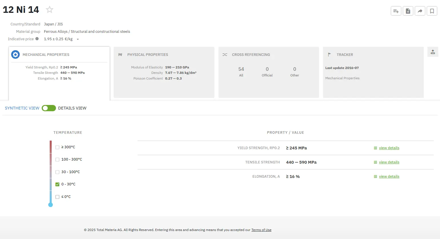
Get a FREE test account at Total Materia Horizon and join a community of over 500,000 users from more than 120 countries.