Fracture Toughness of Carbon Steels: Part One
Abstract
Fracture toughness is used as a design parameter to establish safe, efficient performance levels for mechanical equipment. Fracture toughness, in the most general of definitions, is the ability of a material to withstand fracture in the presence of cracks.
This article presents a review of important modes of fracture and "classical" microstructures and compositions in different types of steel.
Modern technology has many challenges for the scientist, engineer, or designer of the machinery used by the people of the world. Because mechanical equipment is often used at or near design limitations, great care must be employed in selecting the proper materials to use for a particular design application.
The need for high-performance materials in such industries as aerospace and power generation has advanced the use of design parameters in the evaluation of material behavior. In particular, fracture toughness is used as a design parameter to establish safe, efficient performance levels for mechanical equipment. Fracture toughness, in the most general of definitions, is the ability of a material to withstand fracture in the presence of cracks.
On the other hand fracture toughness is an indication of the amount of stress required to propagate a preexisting flaw. It is a very important material property since the occurrence of flaws is not completely avoidable in the processing, fabrication, or service of a material/component. Flaws may appear as cracks, voids, metallurgical inclusions, weld defects, design discontinuities, or some combination thereof.
Since engineers can never be totally sure that a material is flaw free, it is common practice to assume that a flaw of some chosen size will be present in some number of components and use the linear elastic fracture mechanics (LEFM) approach to design critical components. This approach uses the flaw size and features, component geometry, loading conditions and the material property called fracture toughness to evaluate the ability of a component containing a flaw to resist fracture. A parameter called the stress-intensity factor (K) is used to determine the fracture toughness of most materials.
It is useful first to present a brief survey of important modes of fracture and "classical" microstructures and compositions in different types of steel.
Transgranular Cleavage of Low-carbon Steels
This term will be used to describe steels which are essentially plain-carbon with, perhaps, up to 0.6% silicon and/or manganese, having carbon contents less than 0.2%, and which have been wrought and cooled from the austenite range (e.g., normalized, annealed).
The rate of cooling controls both the ferrite grain diameter, d, and the thickness of grain-boundary carbide films, co. A survey of published data has shown that co (defined roughly as the thickness corresponding to the 95% of the distribution) increases monotonically with d. For higher carbon contents in the range, increasing amounts of pearlite are also observed in the microstructure, but the thicknesses of individual cementite plates in the pearlite are less than those of the grain-boundary cementite films.
For a given carbon content, the yield strength, σy, of a low-carbon steel increases with decrease in grain size, following the Petch relationship
σy = σi +kTY d-1/2
where σi is the friction stress and kTY (tension) has the value 0.7 MPa·m1/2 for as-cooled conditions. The yield stress also increases with the amount of pearlite and with the amount of Mn or Si in solid solution.
Transgranular Cleavage of Spheroidised Steels
For some theoretical analyses, it is easier to consider a microstructure in which the cementite is distributed as spheroidal particles, rather than as plates at grain-boundaries or in pearlite colonies. Suitable distributions may be obtained by quenching plain carbon or low-alloy steels and tempering at temperatures of the order of 700°C, to ensure that all carbides are fully spheroidised. The yield stress in microstructures which contain a significant volume fraction of spheroidal cementite particles is controlled less by the ferrite grain size and more by the particle spacing, λ.
According to the simple Orowan-bowing model, it would be expected that σy ∞λ-1, but general tangling of dislocations around particles tends to produce an effective refinement of the grain size to a cell size of diameter λ, and it is possible to obtain forms closer to σy ∞λ-1/2. Pile-ups of grain-diameter length do not occur, although pile-ups of length λ can perhaps be contemplated.
Transgranular Cleavage of High-Strength Structural Steels
This term is taken to include steels of yield stress greater than 400 MPa, which have to be fabricated by welding and in which hardenability must be controlled to avoid hydrogen cracking in the heat-affected zone (HAZ).
At the lower end of the strength range, the steels are based on, roughly, 0.15% C, 1.5% Mn, with small additions of Nb, V or Al, and may be controlled rolled or normalized in plate or section form, although transforming to bainitic products in the HAZ. They are often supplied to a carbon equivalent, C.E., given by
C.E.(%)= C + Mn/6 + (Cr+Mo+V)/5 + (Cu+Ni)/15
A typical stipulation would be that the C.E. should not exceed 0.43. As strength requirements are increased, it is necessary to employ quenching and tempering in conjunction with more hardenable steels.
Well-known examples are A533B nuclear pressure vessel steel (approx. 0.23C-1.5Mn-0.5Mo-0.5Ni), HY80 submarine-hull steel (0.15C-3Ni-1.5Cr-0.4Mo) and HY130 (0.1 C-5Ni-0.5Cr-0.5Mo). This last composition has a yield strength of 1 GPa and may be regarded as the upper limit for conventional welded structures, although G90 maraging steel (0.01C-18Ni-8.5Co-3.25Mo-0.3Ti-0.1AI) which has a yield strength of 1.5 GPa has been used for military bridges.
Generally, however, there is a natural limit to the use of high yield strengths, because the economic section sizes become so slender that they are prone to buckle. The microstructures of as-welded HAZ’s in such steels may be described as martensitic or bainitic "laths" which are found in "packets" which sub-divide the original austenite grain (see Figure 1). Within an individual packet, the laths appear to have similar (or twin-related) orientations, but significant changes in orientation occur at packet boundaries.
The size of the largest packet in a grain is a substantial fraction (greater than 0.5) of the austenite grain size, and increases in a similar fashion with austenitizing temperature. The laths are narrow (0.2~0.6 μm wide) regions of transformation product, bounded by walls of high dislocation density. Both lath width and dislocation density in the walls would appear to depend on hardenability and temperature of transformation.
It is claimed that the yield stress of a lath/packet microstructure is a function of lath width, dL, and follows a Petch-type relationship, but the variation in lath width available to test this rigorously is small. For some hardenable steels, such as HY80, it is possible, at intermediate cooling rates, to obtain a mixed upper bainite/martensite microstructure in the HAZ.
Transgranular Cleavage of HSLA Forging Steels
These are designed on a hardenability basis, with carbon contents in the range roughly 0.28-0.4% and sufficient additions of Ni or Cr to give a fully martensitic microstructure when quenched in pieces of the desired section thickness.
The steels are tempered to produce the optimum combination of strength and toughness. The as-quenched microstructure is predominantly a lath/packet martensite, although, if both C and Ni are high, small patches of plate martensite can be found.
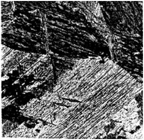
Figure 1: Lath martensite in A533B quenched from 1250°C (x170) (x5/7)
On tempering at temperatures up to about 450°C, carbide is precipitated in two 'distinct morphologies. Initially, ε-carbide forms inside the laths, assuming a crystallographic habit with the matrix.
At temperatures above approx. 200°C, this transforms in situ to cementite and further cementite begins to form (possibly from retained austenite) in lath-boundaries, packet-boundaries and prior austenite grain-boundaries.
For tempering temperatures of 300°~350°C (corresponding to a toughness minimum), the cementite distribution is bimodal: both intra- and inter-laths (see Figures 2 and 3). At tempering temperatures above 450°C, self-diffusion and alloying-element diffusion rates become significant; the transformation dislocations are removed and are eventually replaced by ferrite grain-boundaries, and cementite is replaced by alloy carbides.
Even for a tempering treatment of 1 h at 600°C, however, the plate-like (or needle-like) form of inter-lath/interpacket carbide still persists. A similar tempering sequence is followed also in high-strength structural steels, although, if these are rather lean in alloy content, the initial microstructure may already contain dispersed carbides in bainitic, or auto-tempered martensitic form.
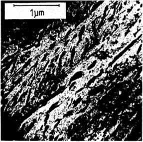
Figure 2: Intra-lath and inter-lath cementite in Fe-0.6C quenched and tempered at 350°C, taken by transmission electron micrograph
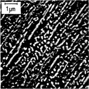
Figure 3: As Figure 2, taken by scanning electron micrograph
Access Fracture Mechanics Properties of Thousands of Materials Now!
Total Materia Horizon includes a unique collection of fracture mechanics properties such as K1C, KC, crack growth and Paris law parameters, for thousands of metal alloys and heat treatments.
Get a FREE test account at Total Materia Horizon and join a community of over 500,000 users from more than 120 countries.