Contribution of Fracture Mechanics to Material Design: Part One
Abstract
Traditional design implements the safety factor (SF) as a safety measure of a structure. The allowed stresses are calculated from the Yield Stress (YS) or Ultimate Tensile Stress (UTS) and SF ratio. This approach gives satisfactory results only for structures in which plastic yielding is expected to occur, i.e. when no brittle fracture is expected.
A.A. Griffith was the first to introduce in 1920 both the importance of the presence of defects, named cracks, and the first calculations for cracked solid materials. Since then, further modifications and improvements have established fracture mechanics as a reliable methodology for the prediction of service behavior of materials and components.
Failure of a component or a structure can be attributed to numerous reasons, as showed in Figure 1; causes of failure can be classified in two groups, i.e. causes driven by design activities (positions 2 and 3) and causes driven by fabrication procedure in all steps (positions 1, and 4 to 6).
It can be concluded that the major reasons for failure are related to fabrication, service, and maintenance, i.e. activities depending on “human factor”. For this group of factors, the performance and reliability of structures can be improved by the implementation of more strict quality assurance and better controlled operations.
On the other hand, about 29.3% of all failures are caused by poor design or standards. Therefore, this segment has come into the focus of research efforts, primarily due to high price and importance of vital structures, such as nuclear and power plants, aerospace, and military applications.
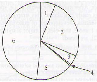
Figure 1: Causes for failure of steel structures: 1-poor quality of material (6.3%); 2-inappropriate project solution (design) (25.1%); 3-doubious standards (4.2%); 4-inappropriate strength/properties (0.4%); 5-irresponsible manipulation, service and maintenance (15.7%); 6-errors in fabrication and finalization of component/structures (48.3%).
Material design is usually based on the following requirements:
- mechanical properties: strength YS-yield strength and/or UTS- ultimate tensile strength), elongation, deflection, toughness;
- technological properties: weldability, formability, machinability;
- physical properties: corrosion resistance, wear resistance, electrical and thermal conductivity.
Traditional design implements the safety factor (SF) as a safety measure of a structure. The allowed stresses are calculated from the Yield Stress (YS) or Ultimate Tensile Stress (UTS) and SF ratio. This approach gives satisfactory results only for structures in which plastic yielding is expected to occur, i.e. when no brittle fracture is expected.
The YS to UTS ratio was also used, due to the "strength reserve" between values of YS and UTS, i.e. if plastic yielding occurs, large strain and strength increase can be measured. This approach is almost abandoned, because for example microalloyed steels have much higher YS in comparison to carbon or carbon-manganese steels, while the UTS is of similar values. These steels have strongly questioned the reliability of classic design calculations. Both approaches have not answered to the need of safe design against brittle fracture.
Fracture Mechanics and Materials
A.A. Griffith was the first to introduce in 1920 both the importance of the presence of defects, named cracks, and the first calculations for cracked solid materials. During the next 80 years, modifications and improvements of Griffith's early work have established fracture mechanics as a reliable methodology for the prediction of service behavior of materials and components. Of course, since there is no perfect methodology, fracture mechanics should be used bearing in mind all its limitations.
Fracture condition for an infinite plate with through-thickness crack is given by:

where
KIC - minimal critical stress intensity factor
σ - design stress
a - allowable flow size or flaw detection sensitivity of equipment for defects introduced during fabrication;
This relationship may be used in several ways to design against a component failure. Its significance lies in the fact that the designer must make a decision what is the most important feature in component service and design: (a) materials properties, (b) the stress level, or (3) the crack size that can be tolerated for safe operation of the part. After making the decision, i.e. specifying two parameters in equation 1, the third parameter is easily calculated.
This simple equation has imposed a major challenge to all materials scientists and the development of materials with KIC as high as possible has become a high priority. In Tables 1 and 2, the roles of major alloying elements in steel and (as an example) one Al alloy, are listed.
Table 1: Role of major alloying elements in steel
| Element | |
| C | Extremely potent hardenability agent and solid solution strengthener; carbides also provide strengthening but nucleate cracks. |
| Ni | Extremely potent toughening agent; lowers transition temperature; hardenability agent; austenite stabilizer. |
| Cr | Provides corrosion resistance in stainless steel; hardenability agent in quenched and tempered steels; solid solution strengthener; strong carbide former. |
| Mo | Hardenability agent in quenched and tempered steels; suppresses tempering embrittlement; solid solution strengthener; strong carbide former. |
| Si | Deoxidizer; increase yield point and transition temperature when present in solid solution. |
| Mn | Deoxidizer; forms MnS, which precludes hot cracking, caused by grain-boundary melting of MnS films; lowers transitions temperature. |
| Co | Used in maraging steels to enhance martensite formation and precipitation kinetics. |
| Ti | Strong carbide and nitride former, stabilizer in stainless steels. |
| V | Strong carbide and nitride former. |
| Nb | Strong carbide and nitride former, stabilizer in stainless steels. |
| Al | Strong deoxidizer; forms AlN, which pins grain boundaries and keeps ferrite grain size small. AlN formation also serves to remove N from solid solution, thereby lowering lattice resistance to dislocation motion and lowering transition temperature. |
It is clear that the increase of toughness in steel requires either mechanism of grain refinement and/or alloying with nickel. On the other hand, toughness is not the only requirement for a material. Therefore, the development of materials that can meet all requirements together with reasonably low cost is a long-term challenge. The response of material scientists in the previous century and the contribution of fracture mechanics will be described on the development of steel.
Table 2: Role of major alloying elements in the aluminum alloy 7178-T6
| Element | |
| Zn | Found in Gunier-Preston zone and subsequently in MgZn2 precipitates; strong precipitation-hardening agent |
| Mg | Some Mg2Si formation, but mostly found in MgZn2 precipitates and in solid solution |
| Cu | Exists in solid solution, in CuAl2, and in Cu-Al-Mg type precipitates, and also in Al7Cu2Fe intermetallic compound |
| Fe | Initially reacts to form Al-Fe-Si intermetallic compounds; impurity |
| Si | Initially reacts to form Al-Fe-Si intermetallic compounds; prior to be replaced by Cu. Also forms Mg2Si |
| Cr | Combines with Al and/or Mg form fine precipitates which serve to grain refine |
| Mn | Exact role not clear |
| Sc | Grain refiner |
| RE | Grain refiners |
Access Fracture Mechanics Properties of Thousands of Materials Now!
Total Materia Horizon includes a unique collection of fracture mechanics properties such as K1C, KC, crack growth and Paris law parameters, for thousands of metal alloys and heat treatments.
Get a FREE test account at Total Materia Horizon and join a community of over 500,000 users from more than 120 countries.