Fatigue Properties: Part Two
Abstract
A fatigue fracture will have two distinct regions; One being smooth or burnished as a result of the rubbing of the bottom and top of the crack. The second is granular, due to the rapid failure of the material.
Striations are thought to be steps in crack propagation, were the distance depends on the stress range. Beachmarks on the other hand may contain thousands of striations.
One can determine that a material failed by fatigue by examining the fracture sight. A fatigue fracture will have two distinct regions; One being smooth or burnished as a result of the rubbing of the bottom and top of the crack (steps 1 & 2); The second is granular, due to the rapid failure of the material.
Other features of a fatigue fracture are Beachmarks and Striations. Beachmarks, or clamshell marks, may be seen in fatigue failures of materials that are used for over a period of time, allowed to rest for an equivalent time period and then loaded again as in factory usage. Striations are thought to be steps in crack propagation, were the distance depends on the stress range. Beachmarks on the other hand may contain thousands of striations.
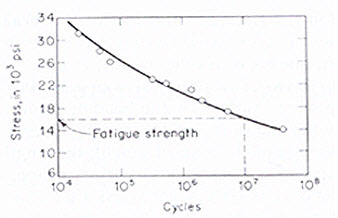
A very useful way to visualize time to failure for a specific material is with the S-N curve. The "S-N" means stress verse cycles to failure, which when plotted uses the stress amplitude, σa plotted on the vertical axis and the logarithm of the number of cycles to failure. An important characteristic of this model as seen in Figure 3 is the fatigue limit.

Figure 3: A S-N Plot for an aluminum alloy
The significance of the fatigue limit is that if the material is loaded below this stress, then it will not fail, regardless of the number of times it is loaded. Material such as aluminum, copper and magnesium do not show a fatigue limit, therefore they will fail at any stress and at any number of cycles. Other important terms are fatigue strength and fatigue life. The stress at which failure occurs for a given number of cycles is the fatigue strength. The number of cycles required for a material to fail at a certain stress in fatigue life.
The rate of fatigue crack propagation is determined by subjecting fatigue-cracked specimens, like the compact specimen used in fracture toughness testing, to a constant-amplitude and cyclic loading. The incremental increase in crack length is recorded along with the corresponding number of elapsed load cycles to acquire the stress intensity (K), crack length (a), and cycle count (N) data during the test. The data is presented in an “a versus N” curve as shown in the image to the right. Various a versus N curves can be generated by varying the magnitude of the cyclic loading and/or the size of the initial crack.
Dependable design against fatigue-failure requires thorough education and supervised experience in structural engineering, mechanical engineering, or materials science. There are three principal approaches to life assurance for mechanical parts that display increasing degrees of sophistication:
- Design to keep stress below threshold of fatigue limit (infinite lifetime concept);
- Design (conservatively) for a fixed life after which the user is instructed to replace the part with a new one (a so-called lifed part, finite lifetime concept, or "safe-life" design practice);
- Instruct the user to inspect the part periodically for cracks and to replace the part once a crack exceeds a critical length. This approach usually uses the technologies of nondestructive testing and requires an accurate prediction of the rate of crack-growth between inspections. This is often referred to as damage tolerant design or "retirement-for-cause".
Fatigue cracks that have begun to propagate can sometimes be stopped by drilling holes, called drill stops, in the path of the fatigue crack. This is not recommended as a general practice because the hole represents a stress concentration factor which depends on the size of the hole and geometry. There is thus the possibility of a new crack starting in the side of the hole. It is therefore always far better to replace the cracked part entirely.
Read more
Access Cyclic Properties of Thousands of Materials Now!
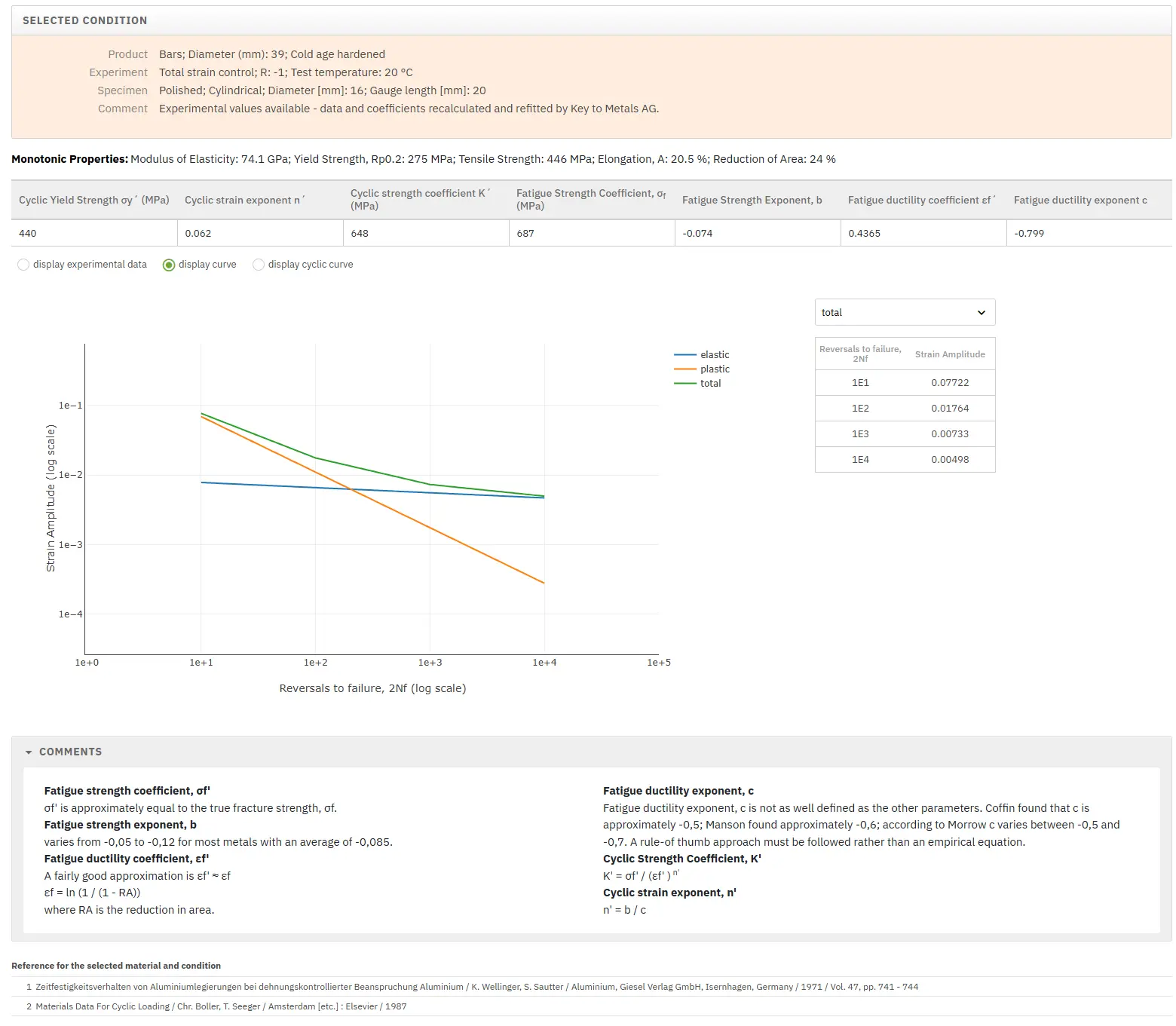
Total Materia Horizon includes a unique collection of fatigue properties of metallic and nonmetallic materials, for both low- and high cycle fatigue.

Get a FREE test account at Total Materia Horizon and join a community of over 500,000 users from more than 120 countries.