Constant temperature transformation TTT curves
Abstract
This article examines the constant-temperature transformation of austenite in steel, focusing on Time-Temperature-Transformation (TTT) curves. It details the methodologies used to study austenite transformation, including specimen heating and dilatometer measurements. The article explores three primary transformation mechanisms - pearlitic, bainitic, and martensitic - and their respective characteristics. Understanding these transformations is crucial for metallurgists in planning and controlling heat-treatment operations. The study includes detailed analysis of transformation behaviors at various temperatures and their implications for steel properties.
Introduction to TTT Curves
The structures formed during the continuous cooling of steel from above Ac3 can be understood best by studying the constant-temperature (isothermal) transformation of austenite, thus separating two key variables: time and temperature. This transformation process can be studied through two primary methods. The first involves heating small specimens above Ac3 to form austenite, then quenching them into a suitable bath (such as liquid tin) at a constant sub-critical temperature. After holding for selected periods, the specimens are withdrawn and rapidly quenched in cold water, converting any untransformed austenite into martensite, which can be estimated microscopically.The second method measures length changes caused by austenite decomposition at constant temperature using a dilatometer.
Transformation Behavior and the TTT Curve
When carbon steel undergoes quenching in baths at constant temperatures, the velocity of austenite transformation varies with temperature. The time required for both the beginning and completion of austenite transformation is plotted against temperature to create what was originally called the Bain "S-curve," now known as the TTT-curve (time-temperature-transformation).
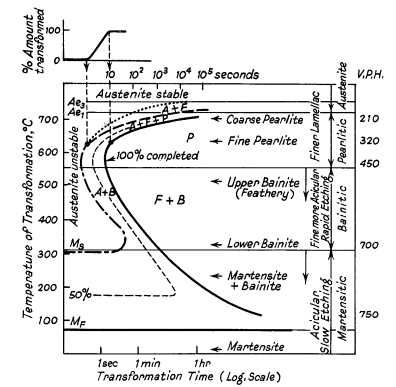
Figure 1: Ideal TTT-curve for 0.65% carbon steel depicting time interval required for beginning, 50% and 100% transformation of austenite at a constant temperature A= Austenite F= Ferrite P = Pearlite B = Bainite
The logarithmic time scale consolidates results into a manageable space. The Ae1 and Ae3 lines represent equilibrium transformation temperatures. Above Ae3, austenite remains completely stable, while between Ae3 and Ae1, it becomes partially unstable. Below Ae1, austenite becomes completely unstable and transforms over time. Notable rapid transformation regions occur at approximately 550° and 250°C.
Transformation Mechanisms
The decomposition of austenite occurs through three distinct, sometimes overlapping mechanisms:
1. Pearlitic Transformation
The TTT diagram (Fig. 1) shows two significant curves in the pearlitic region. The uppermost dotted curve marks the initial formation of ferrite, while the curve immediately below indicates where austenite begins transforming into a ferrite-carbide aggregate. In the high-temperature pearlitic range, the transformation process closely mirrors crystal solidification from a liquid state. This involves the sequential formation and growth of carbide nuclei, followed by ferrite development through side nucleation and growth patterns, as illustrated in Fig. 2a and b.
When the transformation occurs at 700°C, nuclei formation progresses slowly during the initial incubation period. However, once initiated, growth accelerates rapidly, resulting in extensive pearlite colonies that can span multiple austenite grains. As the transformation temperature decreases to 500°C, two significant changes occur: the incubation period shortens, and the resulting pearlite structure becomes notably finer.
At austenite boundaries, numerous nuclei form, though their growth rate diminishes, leading to the formation of nodular troostite (shown in Fig. 2a). In medium carbon steels, this process is accompanied by two distinctive features: a reduction in excess ferrite volume and the development of an acicular or Widmanstätten pattern distribution. The expected quantity of free ferrite following heat treatment can be predicted by examining two factors: the dimensions of the "austenite and ferrite" field and the temperature range between Ae1 and Ae3.
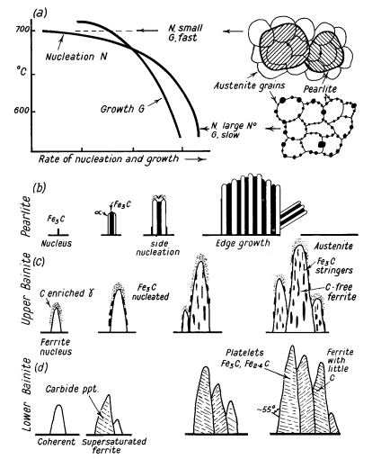
Figure 2: Formation diagrams of pearlite colonies
2. Bainitic Transformation
In the temperature range between 500°C and 350°C, the transformation process begins with the formation of ferrite nuclei that maintain coherency with the austenite matrix. Following this initial formation, cementite precipitates emerge from the carbon-enriched austenite layer, which facilitates continued ferrite growth, as demonstrated in Fig. 2c.
Upper Bainite Formation
In the upper temperature range, carbides develop a distinctive orientation, aligning parallel to the bainite needle's long axis. This alignment creates the characteristic open feathery structure typical of upper bainite.
Lower Bainite Formation
When temperatures drop below 350°C, the transformation sequence changes. Initially, coherent ferrite forms in a carbon-supersaturated state. This is followed by carbide precipitation within the ferrite needle, occurring transversely at a 55° angle. The resulting structure contains Fe2.4C carbide, while the ferrite retains a small amount of dissolved carbon. This lower bainite configuration bears a notable resemblance to lightly tempered martensite, as illustrated in Fig. 2d.
3. Martensitic Transformation
During rapid quenching to approximately 250°C, the temperature decreases so quickly through the nucleation interval that molecular mobility (diffusion) becomes severely restricted, preventing conventional nuclei formation. Instead, austenite undergoes an incomplete transformation into a distorted body-centered structure, forming martensite plates at remarkable speeds (under 0.002 seconds). This transformation occurs through a shearing process rather than traditional nucleation and growth, resembling mechanical twinning with minimal atomic movement but significant internal stress due to shear forces and carbon atom positioning.
As temperature decreases, rising elastic energy induces matrix shearing, which stabilizes the surrounding structure. Additional shear transformations require further temperature reduction and energy input. Consequently, martensite formation depends primarily on temperature rather than time. This process typically leaves some retained austenite in quenched steel, which can be further transformed through sub-zero quenching.
Martensite Start Temperature (Ms)
The martensite formation temperature (Ms) exhibits an inverse relationship with carbon content:
Table 1: Carbon Content (%) - Ms Temperature (°C)
| C % | 0.02 | 0.2 | 0.4 | 0.8 | 1.2 |
| Ms °C | 520 | 490 | 420 | 250 | 150 |
For precise Ms temperature calculations, the Steven and Haynes empirical formula applies:
Ms (°C) = 561 - 474(% C) - 33(% Mn) - 17(% Ni) - 17(% Cr) - 21(% Mo)
Transformation Characteristics
While plastic and elastic stresses facilitate martensite formation, interrupted cooling causes transformation retardation. Upon resuming cooling after stabilization, martensite formation requires lower temperatures to restart. The extent of stabilization depends on multiple factors including holding temperature, duration, prior transformation extent, and alloy composition.
Martensite Morphology
Two distinct forms of martensite exist, depending on carbon content:
- Low carbon steels: Feature lath structures with numerous dislocations
- High carbon steels: Exhibit heavily twinned plates

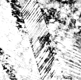
Figure 3. (a) Lathe martensite formed in 0,08°C steel quenched in brine from 100°C (x20000), (b) Twinned martensite in Fe30%Ni (x110000)
Practical Applications
The TTT-curve serves as an invaluable tool for metallurgists, enabling them to:
- Interpret steel's response to specific heat-treatments
- Plan practical heat-treatment operations
- Control limited hardening or softening processes
- Determine appropriate soaking times
Modern Classifications
Current understanding classifies phase transformations into two groups: civilian transformations, where atoms move randomly (like in pearlite formation), and military transformations, characterized by orderly, disciplined movement (as in martensite formation). These transformation patterns extend beyond ferrous alloys, occurring in various non-ferrous systems as well.
Find Instantly Thousands of Heat Treatment Diagrams!
Total Materia Horizon contains heat treatment details for hundreds of thousands of materials, hardenability diagrams, hardness tempering, TTT and CCT diagrams, and much more.
Get a FREE test account at Total Materia Horizon and join a community of over 500,000 users from more than 120 countries.