Relation between CE structure and mechanical properties
Abstract
A useful first attempt to relate composition and structure was shown in Fig. 3 of the article Cast Irons but it had limited use in the foundry. Figure 1 shows a more useful relationship between CE value, structure, tensile strength in 30 mm dia bars and section size. A cylindrical test bar of given dia cools more rapidly than a flat plate of equivalent thickness, hence the section is expressed as bar diameter or section thickness. Line H is the boundary of unmachinable irons while line P is the boundary between soft and pearlitic irons. Thus an iron of carbon equivalent 4,35 should not be made thicker than 20 mm as a bar or 10 mm as a plate to attain a pearlitic iron. To avoid an unmachinable chilled casting the bar should not be less than 8 mm dia or plate less than 4 mm thick.
A useful first attempt to relate composition and structure was shown in Fig. 3 of the article Cast Irons but it had limited use in the foundry. Figure 1 shows a more useful relationship between CE value, structure, tensile strength in 30 mm dia bars and section size. A cylindrical test bar of given dia cools more rapidly than a flat plate of equivalent thickness, hence the section is expressed as bar diameter or section thickness. Line H is the boundary of unmachinable irons while line P is the boundary between soft and pearlitic irons. Thus an iron of carbon equivalent 4,35 should not be made thicker than 20 mm as a bar or 10 mm as a plate to attain a pearlitic iron. To avoid an unmachinable chilled casting the bar should not be less than 8 mm dia or plate less than 4 mm thick.
T S. MPa in 30 mm dia. bar
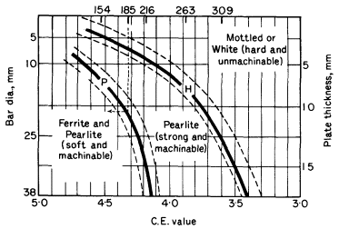
Figure 1. Diagram relating section size, CE value, tensile strength and structure (After BCIRA)
A melting furnace usually produces iron of a constant CE value and silicon is the element normally used to control chill. Alloying elements are added to cast iron to confer special properties and also to control the chill.
Formation of graphite
Flake. Neglecting the effect phosphorus, and the presence of primary austenite dendrites, the successive stages in the growth from the liquid of flake graphite is shown in Fig. 2a The eutectic begins to solidify at nuclei from each of which is formed a roughly spherical lump, referred to as a eutectic cell. In this cell there has been simultaneous growth of austenite and graphite, the latter being in continuous contact with the liquid. The normal appearance of graphite in a micrograph suggests that the structure is made up of a number of separate flakes, but now it is considered that within each eutectic cell there is a continuous branched skeleton of graphite, like a cabbage. The skeleton is branched more frequently with a rapid radial growth of the cell such as occurs when increasing the rate of cooling of an iron which produces undercooling, and therefore finer graphite in the micrograph (Fig. 3).
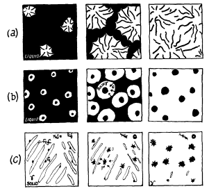
Figure 2.
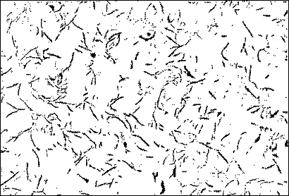
Figure 3. Medium size graphite outlining dendrites (x60)
The diameter of a eutectic cell, therefore, has a major effect on mechanical properties, e.g. the greater the number of cells per unit volume the higher the tensile strength, but soundness is affected adversely. Superheating or holding time of the molten iron reduce the number of nuclei, while inoculants such as ferro-silicon and also sulphur increase nuclei.
Spheroidal. Fig. 2b show the growth of spherulitic graphite in a magnesium-treated iron. In this case the spherulitic graphite is quickly surrounded by a layer of austenite and growth of the spheroid occurs by diffusion of carbon from the liquid through the austenite envelope. If diffusion distances become large there will be a tendency for the remaining liquid to solidify as white iron eutectic, hence inoculation in this iron is highly desirable in order to increase the number of graphite centres. Temper carbon nodules. At the malleabilising temperature (800-950°C) the solid white iron consists of eutectic matrix of cementite, austenite and sulphide inclusions. Nucleation of graphite then occurs at austenite cementite interfaces and at sulphide inclusions. The cementite gradually dissolves in the austenite and the carbon diffuses to the graphite nuclei. The MnS tends to form a flake aggregate and the FeS a spherulitic nodule (Fig. 2c).Micro-structure of cast iron
In preparing the specimens care is required, otherwise, erroneous results might arise. The graphite is readily removed during polishing and in this case the cavities can be either burnished over or enlarged. The various types of micro-structure can be classified into groups without considering the presence of phosphorus.
The graphite can vary in size and form as illustrated in Figs. 3-5. The coarse flaky graphite is found in common iron, while the fine curly type, frequently outlining the dendrites, is found in high-class iron, especially when superheated before casting. Spheroidal graphite is found in magnesium treated irons (Fig. 6). The nodular form is found in annealed irons in which the cementite has decomposed at 800-950°C. Thus we have:
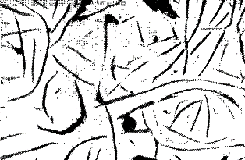 | 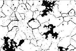 |
| Figure 4. Coarse graphite flakes. | Figure 5. Temper carbon in a malleable iron; ferrite crystals etched (x 100) |
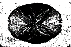 | 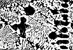 |
| Figure 6. Enlarged view of graphite spheroid. Polarised light (x 600) | Figure 7. Hypo-eutectic white cast iron, cementite and pearlite(black) |
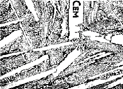 | 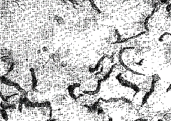 |
| Figure 8. Hyper-eutectic white cast iron (x 100). White primary crystals of cementite in eutectic | Figure 9. Grey iron. High duty; |
| Pearlite + cementite (i.e. eutectic cementite in hypoeutectic irons (Fig. 7) and primary andeutectic cementite in hyper-eutectic irons (Fig. 8) | white, hard, unmachinable. |
| Cementite + graphite + pearlite | mottled, difficult to machine. |
| Graphite + pearlite (Fig. 9) | grey, machinable, high strength. |
| Graphite + pearlite + ferrite (Fig. 4 from the Cast Iron article) | grey, soft, weaker, |
| Graphite + ferrite | grey, very soft, easily machined. |
The ferrite is of course much less pure than that in carbon steels.
Phosphide eutectic
Most cast irons contain phosphorus in amounts varying from 0,03 to 1,5%, consequently another micro-constituent is frequently present in the structure, in addition to those phases mentioned above. It occurs in white irons as a laminated constituent (ternary eutectic), consisting of:
| Iron, 91,19% | Ferrite (with a little phosphorus). |
| Carbon, 1,92% | Cementite, Fe3C. |
| Phosphorus, 6,89 % | Iron phosphide, Fe3P. |
The melting-point is in the region of 960°C, consequently it is the last constituent to solidify and forms islands in the interstices of the dendrites.
Although this constituent is very brittle it does not unduly weaken the iron when in small amounts (up to 1%) due to the fact that continuous cells are not formed round the grains. The structure is illustrated in Fig. 4 from the Cast Iron article which shows the structure of the phosphide eutectic, together with graphite, ferrite and pearlite. Phosphorus will thus form this additional constituent in any of the "grouped" structures already discussed.
Find Instantly Precise Material Properties!
Total Materia Horizon contains mechanical and physical properties for hundreds of thousands of materials, for different temperatures, conditions and heat treatments, and much more.
Get a FREE test account at Total Materia Horizon and join a community of over 500,000 users from more than 120 countries.