Analyzing Failures of Metal Components: Part One
Abstract
Many elements of fracture have been used to describe and categorize the types of fractures encountered in the laboratory and in service. These elements include loading conditions, rate of crack growth, and macroscopic and microscopic appearance of fracture surfaces.
Failure analysis often find itself useful to classify fractures on a macroscopic scale as ductile fractures, brittle fractures, fatigue fractures and fractures resulting from the combined effects of stress and environment.
Many elements of fracture have been used to describe and categorize the types of fractures encountered in the laboratory and in service. These elements include loading conditions, rate of crack growth, and macroscopic and microscopic appearance of fracture surfaces.
Failure analysis often find itself useful to classify fractures on a macroscopic scale as ductile fractures, brittle fractures, fatigue fractures and fractures resulting from the combined effects of stress and environment. The last group includes stress-corrosion cracking and liquid-metal embrittlement, interstitial embrittlement, corrosion fatigue and stress rupture.
Ductile Fractures
Ductile fractures are characterized by tearing of metal accompanied by appreciable gross plastic deformation and expenditure of considerable energy. Ductile tensile fractures in most materials have a gray, fibrous appearance and are classified on a macroscopic scale as either flat-face (square) or shear-face (slant) fractures.
Brittle Fractures
Brittle fractures are characterized by rapid crack propagation with less expenditure of energy than with ductile fractures and without appreciable gross plastic deformation. Brittle tensile fractures have a bright granular appearance, are of the flat-face type, and are produced under plain-strain conditions with little or no necking.
Fatigue Fractures
Fatigue fractures result from cyclic loading, and appear brittle on a macroscopic scale. They are characterized by incremental propagation of cracks until the cross section has been reduced to where it can no longer support the maximum applied load and fast fracture ensues. In the fatigue fracture the fracture surface consists of three distinct zones: a fairly smooth, multiple origin fatigue zone containing "ratchet marks", a low cycle, rougher fatigue zone and a single cycle final fracture zone.
When designing modern equipment to operate in severe environments, a designer is confronted with many complex problems in selecting and evaluating materials, processing, expected loadings and design stresses. Components in turbines, reactors, missiles, submarines and cryogenic equipment may be subjected to such conditions as extremely high or low temperature, corrosive liquids, high vacuum, progressive deterioration due to radiation damage and surface wear. Materials selection must often be confined to a small group of metals for outstanding resistance in one characteristic, such as inertness to the environment in chemical processing equipment. However, many other factors must be considered such as strength, toughness, fabricability and wear resistance, before selection and design can be finalized.
Detailed analysis of failures encountered in developing a prototype (or in a service component) is vital before appropriate changes can be made to assure a reliable product.
In general, service failures may arise from many causes. For mechanical equipment, these causes might be broken down roughly into three categories, as follows:
Design inadequacies. Sharp corners or abnormal stress-raisers, inadequate fasteners, wrong material or heat treatment, unforeseen conditions of service, and lack of accurate stress analysis are included.
Processing and fabrication. About half of these may be due to metallurgical factors such as quench cracks, improper heat treatment, forging or casting defects, nonmetallic inclusions; the other half are due to misalignments, weld flaws, improper machining or assembly, grinding cracks, cold straightening, and the like.
Environmental and service deterioration. These include overloads, chemical attack, wear, corrosion, diffusion, and improper maintenance. A "failure" usually occurs as:
- fracture
- excessive deformation
- deterioration
The failure mechanism is usually a material failure that is controlled by the entire environment and history.
Failures of Category I (design considerations) result from mistakes or incompetence of the designer. Regarding failures due to flaws developed by processing or fabrication (Category II), few, if any, standard tests cover all of the possible inherent defects that may be induced by such operations as casting, forging, welding, machining, grinding, heat treating, plating, chemical diffusion, or careless assembly operations.
Category III failures, caused by deterioration, can not be predicted by standard tests that evaluate materials. In some instances unforeseen vibrations or overload conditions may develop to cause failure. In others, service induced damage may develop fatigue failure. Many service conditions involve extremely rapid rates of heating, or include radiation damage, ablation, corrosion or various types of wear. Deterioration during service in an aggressive environment needs to be given special consideration.
There are many types of surface disintegration, chemical activity or metal transfer that affect stability of the component. These are influenced by the time, temperature and dosage of the critical factors in the environment.
Access Fracture Mechanics Properties of Thousands of Materials Now!
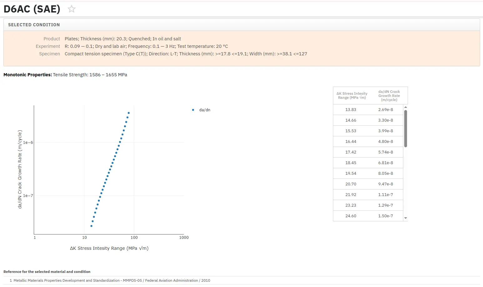
Total Materia Horizon includes a unique collection of fracture mechanics properties such as K1C, KC, crack growth and Paris law parameters, for thousands of metal alloys and heat treatments.

Get a FREE test account at Total Materia Horizon and join a community of over 500,000 users from more than 120 countries.