Steel properties at low and high temperatures
Abstract
Understanding the properties of steel at both low and high temperatures is essential for applications in aerospace and chemical processing. At subzero temperatures, steel exhibits increased tensile and yield strength, but ductility often declines, particularly in ferritic steels. Factors such as carbon content, deformation velocity, and alloying elements significantly influence the transition temperature for brittle fracture. Conversely, at elevated temperatures, creep becomes a critical concern, characterized by slow plastic deformation under constant stress.
This article examines the behavior of steel across temperature extremes, detailing mechanical properties, suitable alloy selections, and implications for design and material selection in demanding environments.
Steel Properties at Low Temperatures
Modern aircraft and chemical processing equipment must operate in subzero conditions, requiring careful consideration of metal behavior down to -150°C. This is particularly important for welded designs, where changes in section and undercutting may occur.
Metals generally exhibit increased tensile and yield strength at low temperatures. However, copper, nickel, aluminum, and austenitic alloys maintain much of their ductility and shock resistance despite this strength increase.
For unnotched mild steel, elongation and reduction of area are satisfactory down to -130°C, but they decline significantly afterward. Ferritic steels experience a sharp drop in Izod value around 0°C (see Figs. 1 and 2).
Factors Influencing Transition Temperature
The transition temperature for brittle fracture can be lowered by:
- Reducing carbon content (ideally below 0.15%)
- Decreasing deformation velocity
- Minimizing notch depth
- Increasing notch radius (minimum of 6 mm)
- Raising nickel content (around 9%)
- Reducing grain size; using steel deoxidized with aluminum to achieve a fine pearlitic structure without bainite is advisable
- Increasing manganese content; the Mn/C ratio should exceed 2:1, preferably 8:1.
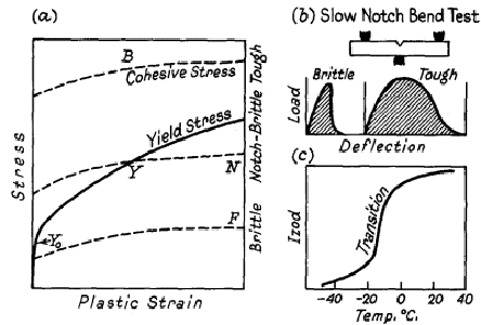
Figure 1.
(a) Yield and cohesive stress curves
(b) Slow notch bend test
(c) Effect of temperature on the Izod value of mild steel
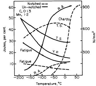
Figure 2. Effect of low temperatures on the mechanical properties of steel in plain and notched conditions
Surface grinding with grit coarser than 180 and shot-blasting can cause embrittlement at -100°C due to work-hardening. This can be corrected by annealing at 650-700°C for 1 hour, which also helps prevent brittle fracture in welded structures by relieving residual stresses.
For temperatures below -100°C or when notch-impact stresses are involved, using an 18/8 austenitic or non-ferrous metal is preferable.
The 9% Ni steel offers an attractive combination of properties at moderate prices, with excellent toughness arising from a fine-grained structure devoid of embrittling carbide networks. These networks dissolve during tempering at 570°C, forming stable austenite islands.
A 4% Mn Ni (rest iron) alloy is suitable for castings down to -196°C. Care should be taken to select plates without surface defects and to ensure freedom from notches in design and fabrication.
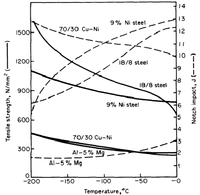
Figure 3. Tensile and impact strengths of various alloys at subzero temperatures
Steel Properties at High Temperatures
Creep, the slow plastic deformation of metals under constant stress, becomes significant in several applications:
- Soft metals like lead and white metal bearings at room temperature.
- Steam and chemical plants operating at 450-550°C.
- Gas turbines functioning at high temperatures.
Creep can lead to fracture at static stresses much lower than those that would break the specimen when loaded quickly, especially in the temperature range of 0.5-0.7 of the melting point Tm.
Stages of Creep
Figure 4a illustrates the variation of metal extension under different stresses, with three recognized stages:
- Primary Stage: Rapid extension occurs at a decreasing rate, influencing total extension and clearances.
- Secondary Period: Creep occurs at a constant rate, known as the minimum creep rate, which is crucial for applications.
- Tertiary Creep Stage: The rate of extension accelerates, leading to rupture. Avoid using alloys in this stage, as determining the transition from secondary to tertiary can be challenging.
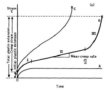
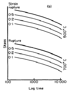
Figure 4.
a) Family of creep curves at stresses increasing from A to C
b) Stress-time curves at different creep strain and repture
The limited information from creep curves becomes clearer when considering a family of curves across operating stresses. As applied stress decreases, the primary stage shortens, the secondary stage extends, and the tertiary stage tends to decrease. Temperature modifications similarly affect curve shapes.
Design data typically consist of curves for constant creep strain (0.01-0.03%, etc.), relating stress and time for specific temperatures. It's critical to clarify whether the data pertains to the secondary stage alone or includes the primary stage (see Figure 4b).
Designers of plants operating at high temperatures must carefully evaluate maximum permissible strains and plant lifespan. The allowable amounts of creep vary by application and service conditions. Examples for steel include:
| Application | Rate of Creep (mm/min) | Time (h) | Maximum Permissible Strain (mm) |
| Turbine rotor wheels, shrunk on shafts | 10-11 | 100,000 | 0.0025 |
| Steam piping, welded joints, boiler tubes | 10-9 | 100,000 | 0.075 |
| Superheated tubes | 10-8 | 20,000 | 0.5 |
In missile design, data is required at higher temperatures and stresses over shorter durations (5-60 minutes) than typical creep tests. This data is often presented as isochronous stress-strain curves.
Creep tests
Long-term applications necessitate extensive testing to obtain reliable design data. Extrapolating from short-term tests can be risky, as they may not capture all structural changes, such as carbide spheroidization. However, short-term tests are valuable for alloy development and production control.
Long-Time Creep Tests
Uniaxial tensile stress is applied using a lever system to a specimen situated in a tubular furnace with precise temperature control. A sensitive mirror extensometer (Martens type) measures creep rates as low as 1×10−81 \times 10^{-8}1×10⁻⁸ strain/h. From tests at a single temperature, a limiting creep stress is estimated for a small creep rate, incorporating a safety factor in design.
Short-Time Tests
The rupture test determines time-to-rupture under specified conditions of temperature and stress, with approximate strain measurements taken via a dial gauge, as total strain may reach around 50%. This test is useful for evaluating new alloys and has direct applications in design where creep deformation is acceptable, but fracture must be prevented.
Jetzt Kriecheigenschaften von Tausenden von Materialien abrufen!
Total Materia Horizon enthält die größte Datenbank mit Kriechdaten wie Streckspannung und Zeitstandfestigkeit bei verschiedenen Temperaturen für Tausende von Metalllegierungen und Polymeren.
Holen Sie sich ein KOSTENLOSES Testkonto bei Total Materia Horizon und schließen Sie sich einer Gemeinschaft von über 500.000 Benutzern aus mehr als 120 Ländern an.