Fracture Mechanics: Part Three
Abstract
Linear elastic fracture mechanics (LEFM) principles are used to relate the stress magnitude and distribution near the crack tip to (1) remote stresses applied to the cracked component, (2) the crack size and shape, and (3) the material properties of the cracked component.
This article briefly describes background of Linear Elastic Fracture Mechanics.
LEFM Assumptions
Linear elastic fracture mechanics (LEFM) is based on the application of the theory of elasticity to bodies containing cracks or defects. The assumptions used in elasticity are also inherent in the theory of LEFM: small displacements and general linearity between stresses and strains.
In the general form of the LEFM equations a singularity exists such that as r, the distance from the crack tip, tends toward zero, the stresses go to infinity. Since materials plastically deform as the yield stress is exceeded, a plastic zone will form near the crack tip.
The basis of LEFM remains valid, though, if this region of plasticity remains small in relation to the overall dimensions of the crack and cracked body.
Loading Modes
There are generally three modes of loading, which involve different crack surface displacements (see Fig. 3). The three modes are:
| Mode 1: | opening or tensile mode (the crack faces are pulled apart) |
| Mode 2: | sliding or in-plane shear (the crack surfaces slide over each other) |
| Mode 3: | tearing or anti-plane shear (the crack surfaces move parallel to the leading edge of the crack and relative to each other) |
The following discussion deals with Mode 1 since this is the predominant loading mode in most engineering applications. Similar treatments can readily be extended to Modes 2 and 3.
 Figure 3. Three loading modes
Stress Intensity Factor
The stress intensity factor, K, which was introduced in Eq. 1, defines the magnitude of the local stresses around the crack tip. This factor depends on loading, crack size, crack shape, and geometric boundaries, with the general form given by
 |
(2) |
where:
s = remote stress applied to component (not to be confused with the local stresses, sij, in Eq. 1)
a = crack length
f (a/w) = correction factor that depends on specimen and crack geometry
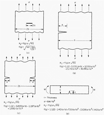
Figure 4 gives the stress intensity relationships for a few of the more common loading conditions. Stress intensity factors for a single loading mode can be added algebraically. Consequently, stress intensity factors for complex loading conditions of the same mode can be determined from the superposition of simpler results, such as those readily obtainable from handbooks. 
| Figure 4. | Stress intensity factor for |
| (a) Center-cracked plate loaded in tension, | |
| (b) Edge-cracked plate loaded in tension, | |
| (c) Double-edge-cracked plate loaded in tension | |
| (d) Cracked beam in pure bending |
Per saperne di più
Accedi immediatamente alle proprietà di meccanica della frattura di migliaia di materiali!
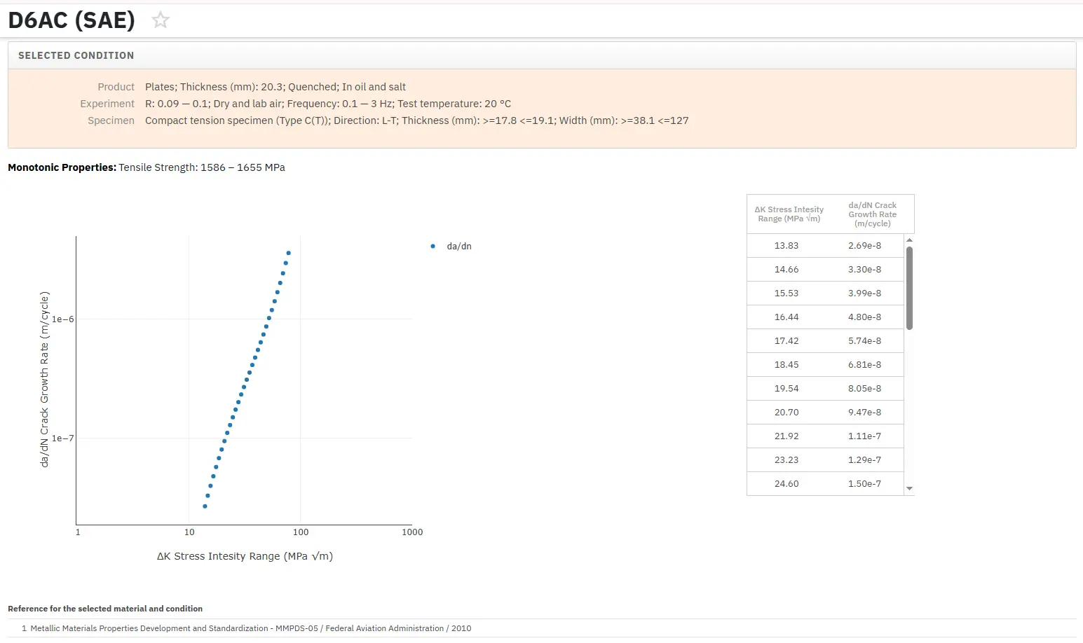
Total Materia Horizon include una raccolta esclusiva di proprietà della meccanica della frattura, come K1C, KC, crescita delle cricche e parametri della legge di Paris, per migliaia di leghe metalliche e trattamenti termici.

Ottieni un account di prova GRATUITO su Total Materia Horizon e unisciti a una comunità di oltre 500.000 utenti provenienti da più di 120 paesi.