Hydro-Forming Process of Steel: Part One
Abstract
One of these new processes is tube hydroforming and although the development of this process for the automotive industries is relative new, many process variables have been studied, including; friction, material properties, pressures and the displacement path during the process.
Hydroforming uses fluid pressure in place of the punch in a conventional tool set to form the part into the desired shape of the die.
INTRODUCTION
Industries, mainly automotive industries, have been looking for new processes to reduce production costs and at the same time to develop new products with lower-weights. One of these new processes is tube hydroforming and although the development of this process for the automotive industries is relative new, many process variables have been studied, including; friction, material properties, pressures and the displacement path during the process.
Some Hydroforming History
The story of how tube hydroforming came to be used as it is today for large structural parts has several beginnings. First, the process most commonly used today is based on the one used for making copper plumbing T's, which starts with a straight tube, uses high internal fluid pressure to expand and directly form the part, and then pushes more material into the end to compensate for wall stretching. Less than 15 years ago, this process was adapted to make even larger structural parts. Distinguishing features of this process are:
- Die is closed before introducing fluid
- Fluid is the primary forming medium
- Cross section expands
- Relatively high pressure (usually greater than 20,000 PSI)
The second origin of this process was a separate development 15 to 20 years ago motivated by the need to address product design and forming limitations and dimensional instability.
A process (Process A, Figure 1) was developed specifically for larger structural parts and was the real beginning of using hydroforming for this purpose. In this process, the tube is filled with low-pressure fluid (one-third to one-fifth the pressure used for the earlier plumbing T process) before the die is fully closed. Water acts as an aid to prevent collapse while the forming die closes, and in this case the die is the primary former.
Normal design practice uses a constant periphery along the part while the shape changes. (The final forming pressure, while higher than when the die is closing, is one-third to one-fifth the pressure used for the earlier ‘T’ process.) The final part's periphery essentially equals that of the start tube.
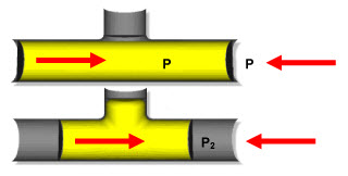
Figure 1: Top, Hydroforming Developments Top - Process A; Bottom - Process B
Subsequent to this development, the T-making process (Process B, Figure 1) was modified to serve the emerging structural parts market. For many parts either process is suitable. The challenge is to know which is best for a particular application and more importantly, to determine the most advantageous approach for the best balance of performance, quality, and cost.
Because Process B is used by more companies, designers often assume that it is the better process for making all parts. This assumption is a dramatic oversimplification that prevents achieving the most efficient and effective part possible.
What is Hydroforming?
Hydroforming uses fluid pressure in place of the punch in a conventional tool set to form the part into the desired shape of the die. The technique is very useful for producing whole components that would otherwise be made from multiple stampings joined together. For example, a typical chassis component that would normally be made by pressing up to six channel sections and joining by spot welding can be hydroformed as a single part. Considerable mass savings are possible through eliminating the flanges required for welding and using thinner steel and yet still maintaining stiffness owing to the elimination of the discontinuous spot-welded joints.
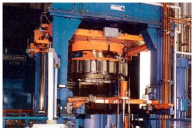
Figure 2: The high pressure hydroforming machine
Acceptance of Hydroforming
Hydroforming is already widely used - in the US, more than a million engine cradles a year are produced using hydroforming processes, and in Europe the technology is being used in sub-frames for models such as Ford’s Mondeo and General Motors’s Vectra. Some 2.8 million components a year for one of Chrysler’s model are produced by hydroforming, too. However, as hydroforming - particularly high-pressure hydroforming - is at the frontier of modern steel technology, many designers and engineers still need convincing of its capabilities.
Types of Hydroforming
There are four main types of hydroforming:
- Hydroforming of tubes, usually at low pressure, is the most widely used technology at present, with hydroformed tubular parts offering improved integrity and structural performance.
- Low pressure hydroforming simply re-shapes tubes, producing a very good shape, but is not as useful if better cross-section definition is required.
- High-pressure hydroforming, totally changes the tube shape and alters the length to circumference ratio by up to 50%. It gives very good tolerance control, being a highly robust process.
- Panel hydroforming at high pressures is used in the aerospace industry, and is expected to be used for applications in the automotive industry in which hydroforming is needed to get the right material flow.
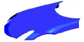
Figure 3: Hydroformed Sheet Metal Part
Hydroforming basically is a technique that uses a fluid either to form or aid in forming a part from ductile metal. Figure 3 shows a part that was hydroformed from sheet metal.
However, the most common type of hydroforming used, tube hydroforming changes the cross-sectional shape of a tube from the normal round to other shapes that change along the part's length (Figure 4).
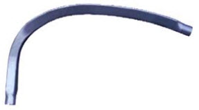
Figure 4: Hydroformed Tube Part
En savoir plus
Accédez en quelques instants aux propriétés des pièces forgées !
Total Materia Horizon contient des milliers de matériaux forgeables, avec leurs propriétés mécaniques et physiques, courbes de formabilité y compris en haute température pour la forge à chaud, et bien plus.
Profitez d’un compte d’évaluation GRATUIT sur Total Materia Horizon et rejoignez notre communauté qui compte plus de 500.000 utilisateurs dans plus de 120 pays.