Friction Stir Welding of Steel: Part Three
W.M. Thomas, P.L. Threadgill and E.D. Nickolas, TWI Ltd, Cambridge, United Kingdom
Abstract
The article describes mechanical properties, weld integrity and microstructure of a low carbon steel and a low carbon 12% chromium alloy steel. In general, mechanical testing and metallographic examinations showed good properties and reasonably uniform shaped double-sided weld profiles with no evidence of buried defects.
Weld Integrity of Low Carbon 12%Chromium Alloy Steel
Cross-weld tensile tests recorded an ultimate tensile stress of around 539 to 541 N/mm2 with failure occurring in the parent metal well away from the joint or the HAZ region as shown in Figure 1. Acceptable transverse face and root bends (bends with first pass in tension and bends with second pass in tension), typically achieved 180°, see Figure 2.
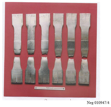
Figure 1: Cross-weld tensile test samples (3 off weld surfaces machined to uniform thickness before testing 3 off as welded)
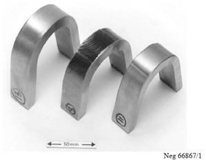
Figure 2: Typical bend test results in 12 mm thick alloy steel plate, showing parent metal, and first pass and second pass in tension
Metallographic examination of selected sections, typically as shown in Figure 6 (see Friction Stir Welding of Steel: Part Two) shows a reasonably uniform shaped double-sided weld profile with no evidence of buried defects.
Average hardnesses were:
Parent metal - 158HV10
HAZ - 280HV10
TMAZ - 230HV10
Weld Integrity of Low Carbon Steel
The cross-weld tensile tests gave an ultimate tensile stress of around 453 to 457 N/mm with failure occurring in the parent metal well away from the joint or HAZ region, broken tensiles are shown in Figure 3. Transverse 180° side bend tests are shown in figure 14.
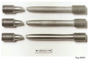
Figure 3: Tensile test specimens of carbon steel FSW butt welds, showing failure in the parent metal away from the weld and HAZ
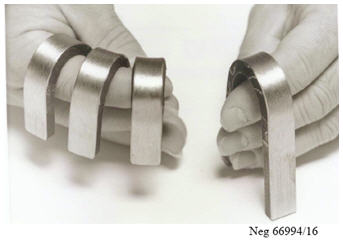
Figure 4: Three 180° side bends in low carbon steel FSW butt joints, plus one comparison parent metal bend
Metallographic examination of selected revealed a flow configuration (see Figure 7 within Friction Stir Welding of Steel-Part Two) not unlike those found on certain aluminium alloy welds. A reasonable shaped weld profile no evidence of buried defects, but some tool wear debris was observed.
Average hardnesses were:
Parent metal - 131HV10
HAZ - 149HV10
TMAZ - 158HV10
Low carbon 12% Chromium Alloy steel
The weld region exhibited two distinct microstructural zones. One of these is the central weld thermomechanically affected (TMAZ) zone, which had transformed, with associated recrystallisation and grain growth. On both sides of the (TMAZ) central weld zone a HAZ region showed some transformation close to the weld but showed no evidence of grain growth. Further out, towards the parent material, the HAZ still showed a degree of tempering, but had not transformed. The HAZ zones on either side were similar in all features. Typical of this type of steel, the parent material showed a very fine ferritic/martensitic structure.
Within the TMAZ a range of ferrite and martensite structures had developed, a typical example is shown in Figure 5. Some light etching bands were present, towards the top of each weld pass. Energy dispersive x-ray micro analysis of these bands indicated the presence of some tool debris. Longitudinal weld sections, however, confirmed that no measurable reduction in weld depth had occurred after steady state welding conditions had been established. There was no evidence of buried defects within the weld region.
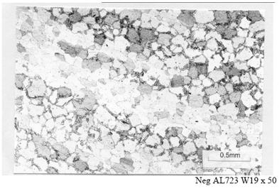
Figure 5: Microstructural bending in TMAZ weld region, showing banded two phase martensite and ferrit structure (12% chromium alloy steel weld)
Low Carbon Steel
The microstructure of the parent steel consisted of the expected ferrite.pearlite grains. The subcritical HAZ showed the expected spheroidization of pearlite, and the intercritical HAZ showed substantial grain refinement resulting from the partial transformation to austenite. The higher temperature supercritical HAZ in the centre of the weld had transformed to a bainitic/ferritic microstructure, with no evidence for martensite transformation.
The boundary between the HAZ, and the TMAZ (i.e. the point of which plastic deformation owing to the welding process first occurred) was difficult to identify, as no evidence of deformation without recrystalisation was observed. This suggests that the HAZ/TMAZ boundary occurred in the region heated above the AC3 temperature. This is in accordance with the peak temperature reached during friction stir welding of low carbon steel, which is probably around 1000-1100°C. A typical microstructure from the centre of the weld (in the TMAZ) is shown in Figure 6a, while Figure 6b shows the HAZ in the region of the AC3 isotherm, where areas of partial and complete transformation to austenite during the welding cycle are apparent.
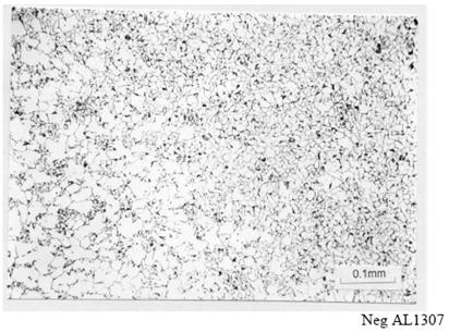
Figure 6a: Banding between partially and completely transformed HAZ in friction stir welding in low carbon steel
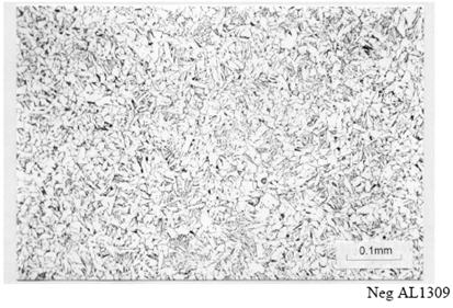
Figure 6b: Microstructure of centre of friction stir weld in low carbon steel
Unlike the 12% chromium alloy steel, there was some evidence of tool debris within the weld region of the carbon steel examined, although examination of the tool after welding showed little wear. The debris existed as fine inclusions, exerting no apparent on the microstructure of the weld. It is needed.
The parent hardness of about 131 HV10 increases across the weld to a maximum of 160HV at the centre. These low values suggest the material was in the hot rolled condition before welding.
Accédez en quelques instants aux matériaux de soudage !
Total Materia Horizon contient des milliers de matériaux d’apport et électrodes avec leur propriétés à l’état livré et soudé.
Profitez d’un compte d’évaluation GRATUIT sur Total Materia Horizon et rejoignez notre communauté qui compte plus de 500.000 utilisateurs dans plus de 120 pays.