Cryogenic Treatment of Steel: Part One
Abstract
Cryogenic treatment significantly enhances the service life of steel components through controlled exposure to extremely low temperatures. This methodology, established in aerospace applications over 30 years ago, produces remarkable improvements particularly for wear-dependent materials like tool steels. The success of cryogenic processing depends on precise control of critical parameters including temperature profile, treatment duration, and subsequent tempering practices. This article examines the fundamental principles of cryogenic treatment, compares cold treatment versus deep cryogenic processing, and provides evidence of substantial performance improvements in treated materials as demonstrated by increased wear resistance and extended service life.
Introduction to Cryogenics
The word "cryogenics" derives from the Greek words "Kryos" (meaning cold) and "Genes" (meaning born). According to the Cryogenics Society of America, cryogenic temperatures are defined as those below 120K (-244°F, -153°C). Cryogenic treatment refers to the process of subjecting materials to subzero temperatures (below 0°C) to enhance service life through beneficial morphological changes that occur during treatment.
Originally developed for aerospace applications, cryogenic processing has been utilized for over 30 years to improve the properties of metals. This treatment has proven particularly valuable for extending tool life and enhancing wear resistance in various steel components.
Fundamental Principles of Cryogenic Science
According to thermodynamic laws, absolute zero represents the lowest theoretically achievable temperature, where molecules reach their minimum energy state. Absolute zero equals -273.15°C or -459.67°F, which forms the zero point of the Kelvin thermodynamic temperature scale. In practical terms, the cryogenic region is typically considered to be below approximately 120K (-153°C).
Common gases transform from gaseous to liquid state at atmospheric pressure at specific temperatures known as normal boiling points (NBP), as shown in Table 1. The resulting liquids are called cryogenic liquids or cryogens.
Table 1: Normal boiling points of common cryogenic fluids
| Cryogen | (K) | (°C) | (°R) | (°F) |
| Methane | 111.7 | -161.5 | 201.1 | -258.6 |
| Oxygen | 90.2 | -183.0 | 162.4 | -297.3 |
| Nitrogen | 77.4 | -195.8 | 139.3 | -320.4 |
| Hydrogen | 20.3 | -252.9 | 36.5 | -423.2 |
| Helium | 4.2 | -269.0 | 7.6 | -452.1 |
| Absolute zero | 0 | -273.15 | 0 | -459.67 |
Cold Treatment vs. Cryogenic Treatment
Metal refrigeration treatments fall into two distinct categories: cold treatment and cryogenic treatment. These processes differ significantly in their application parameters and results:
- Cold Treatment: Typically performed at approximately -120°F (-84°C) where parts are held (soaked) for 1 hour per inch of thickness, then allowed to warm in ambient air.
- Cryogenic Treatment: Involves a slow cool-down rate of -5°F per minute (-3°C per minute) from ambient to -320°F (-196°C), followed by a soak period of 24 to 72 hours, and gradual warming to ambient temperature. The cryogenically treated parts then undergo a tempering treatment (300°F to 1000°F or 149°C to 538°C) for a minimum of one hour.
Multiple factors impact how sub-zero treatments affect an alloy. Processing parameters such as time, temperature profile, number of repetitions, and tempering practice interact with material factors including prior heat treatment and alloy composition to determine final results. Table 2 outlines three different sub-zero treatment applications.
Table 2: An overview of sub-zero treatment processes for metals
| Process | Description | Parameters | Objective |
| Shrink fitting | Overall contraction of metals when cooled allows tight assembly of parts | -70 to -120 °C (-90 to -190 °F) until metal is cold throughout | Temporary change in size |
| Cold treatment of steels | Complete martensitic phase transformation | -70 to -120 °C (-90 to -190 °F) for 1 hour per 3 cm of cross-section | - Transformation of retained austenite to martensite - Increase hardness - Dimensional stability |
| Cryotreatment of steels | Cryotreatment temperatures can create sites to nucleate fine carbides that improve wear resistance in tool steels | -135 °C (-210 °F) and below for 34 hours or longer | Improved wear resistance through carbide precipitation |
Figure 1 below illustrates the significant differences in time-temperature cycles among these processes.
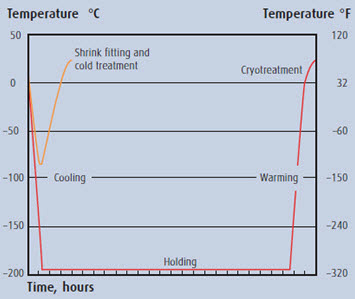
Figure 1: Sub-zero process cycle profiles
Performance Improvements Through Cryogenic Treatment
Table 3 demonstrates the average useful life of various tooling components with and without sub-zero treatment. The "Wear Ratio" parameter—defined as the ratio of life after sub-zero treatment divided by average tool life without treatment—quantifies the improvement this process delivers when correctly applied.
Table 3: Examples of tool life improvements using cryotreatment
| Tooling | Average life before treatment | Average life after treatment | Wear ratio |
| 5-cm end mills used to cut C1065 steel | 64 parts | 200 parts | 3.07 |
| Hacksaw blades used to cut bosses on M107 shells | 4 h | 6 h | 1.5 |
| Zone punches used on shell casings | 64 shells | 5,820 shells | 82.5 |
| Nosing thread dies used in metal working | 225 shells | 487 shells | 2.1 |
| Copper resistance welding tips | 2 weeks | 6 weeks | 3.0 |
| Progressive dies used in metal working | 40,000 hits | 250,000 hits | 6.25 |
| Blanking of heat treated 4140 and 1095 steel | 1,000 pieces | 2,000 pieces | 2.0 |
| Broach used on a C1020 steel torque tube | 1,810 parts | 8,602 parts | 4.75 |
| Broaching operation on forged connecting rods | 1,500 parts | 8,000 parts | 5.33 |
| Gang milling T-nuts from C1018 steel with M2 cutters | 3 bars | 14 bars | 4.67 |
| AMT-38 cut-off blades | 60 h | 928 h | 15.4 |
The substantial differences in wear life between parts cold treated at approximately -80°C (-110°F) versus parts cryogenically treated at -190°C (-310°F) using liquid nitrogen have prompted further research into understanding the underlying mechanisms of improved wear resistance.
Table 4 below provides a comparison of wear resistance improvements in different materials after cold treatment versus cryogenic treatment.
Table 4: Percentage increase in wear resistance after cold treatment and cryotreatment
| AISI | DIN | Material Descriptions | Wear Resistance at -79°C [%] | Wear Resistance at -190°C [%] |
| Materials that showed improvement | ||||
| D2 | – | High carbon/chromium steel | 316 | 817 |
| S7 | – | Silicon tool steel | 241 | 503 |
| 52100 | – | Bearing steel | 195 | 420 |
| O1 | – | Oil hardening cold work die steel | 221 | 418 |
| A10 | – | Graphite tool steel | 230 | 264 |
| M1 | – | Molybdenum high speed steel | 145 | 225 |
| H13 | – | Hot work tool steel | 164 | 209 |
| M2 | – | Tungsten/molybdenum high speed steel | 117 | 203 |
| T1 | – | Tungsten high speed steel | 141 | 176 |
| CPM 10V | – | Alloy steel | 94 | 131 |
| P20 | – | Mold steel | 123 | 130 |
| 440 | – | Martensitic stainless steel | 128 | 121 |
| Materials without improvement | ||||
| 430 | – | Ferritic stainless steel | 116 | 119 |
| 303 | 1.4305 | Austenitic stainless steel | 105 | 110 |
| 8620 | 1.6523 | Case hardening steel | 112 | 104 |
| C1020 | 1.0402 | 0.20% carbon steel | 97 | 98 |
| AQS | – | Gray cast iron | 96 | 97 |
| T2 | – | Tungsten high speed steel | 72 | 92 |
Finden Sie sofort Tausende von Wärmebehandlungsdiagrammen!
Total Materia Horizon enthält Wärmebehandlungsdetails für Hunderttausende von Werkstoffen, Härtbarkeitsdiagramme, Härte-Anlassdiagramme, TTT- und CCT-Diagramme und vieles mehr.
Holen Sie sich ein KOSTENLOSES Testkonto bei Total Materia Horizon und schließen Sie sich einer Gemeinschaft von über 500.000 Benutzern aus mehr als 120 Ländern an.