Friction Stir Welding of Aluminum Alloys: Part Three
W.M. Thomas, I.M. Norris, D.G. Staines and E.R. Wats, TWI Ltd, Cambridge, United Kingdom
Abstract
In conventional rotary FSW, the relative velocity of the tool increases from zero at the probe centre to maximum velocity at the outer diameter of the shoulder. The dual-rotation technique can significantly modify the velocity gradient between the probe centre and the shoulder diameter. This technique provides a differential in rotation speed and the option for rotation in opposite directions. This technique can provide for a more optimized rotational speed for both probe and shoulder.
Dual-rotation Friction Stir Welding
A dual rotation FSW variant provides for a differential in speed and/or direction between the independently rotating probe and the rotating surrounding shoulder as shown in Figure 1.
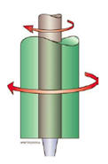
Figure 1: Principle of dual-rotation friction stir welding with rotation of the probe and shoulder in the same direction.
The apparatus used for this investigation is shown sequentially in Figures 2 a & b.
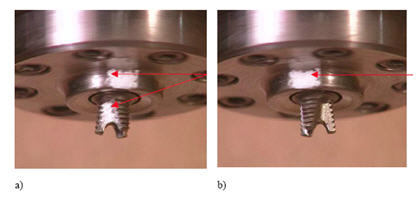
Figure 2: Dual-rotation apparatus complete with white marks on the shoulder and probe to indicate relative rotational movement.
a) White marks on shoulder and probe almost in line.
b) White marks on shoulder and probe moving apart.
The apparatus can enable a range of different rotational speeds to be pre-selected or varied automatically by in-process control to achieve the desired welding conditions. In conventional rotary FSW, the relative velocity of the tool increases from zero at the probe centre to maximum velocity at the outer diameter of the shoulder. The apparatus can enable a range of different rotational speeds to be pre-selected or varied automatically by in-process control to achieve the desired welding conditions.
In conventional rotary FSW, the relative velocity of the tool increases from zero at the probe centre to maximum velocity at the outer diameter of the shoulder. The dual-rotation technique can significantly modify the velocity gradient between the probe centre and the shoulder diameter. This technique provides a differential in rotation speed and the option for rotation in opposite directions. This dual-rotation technique effectively allows for a high probe rotational speed without a corresponding increase in shoulder peripheral velocity. This technique can provide for a more optimized rotational speed for both probe and shoulder.
Dependent on the material and process conditions used, over-heating or incipient melting along the "near shoulder side" of the weld surface of certain friction stir welds can occur. Melting can lead to fusion related defects along the "near shoulder side" weld surface. The dual-rotation technique can be used to reduce the shoulder rotational speed as appropriate and, therefore, help reduce any tendency towards over-heating or melting, while maintaining a higher rotational speed for the probe. A double sided butt weld using non-optimised conditions was made to demonstrate that dual-rotation stir welding is practicable for certain applications. Figure 3 shows the macrostructural features produced by dual-rotation stir welding using a Flared-Triflute™ type probe.
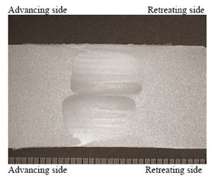
Figure 3: Macrosection of a dual-rotation stir double-sided butt weld in 16 mm thick 5083-H111 aluminium alloy, produced at a welding speed of 3 mm/sec (180 mm/min), using 584 rev/min for the probe and 219 rev/min for the shoulder. The two weld passes were made in opposite directions, with the first pass shown on top.
Guided bend testing demonstrated freedom from gross defects as shown in Figure 4.
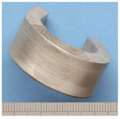
Figure 4: Guided side bend test, carried out on a double-sided butt weld, in 16 mm thick 5083-H111aluminium alloy, achieved 180°.
Figure 5, shows the appearance of the weld surface that is formed beneath the tool shoulder after dual-rotation stir welding.
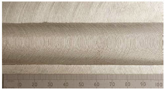
Figure 5: Surface appearance of dual-rotation stir weld made in 16 mm thick 5083-H111 aluminium alloy at a welding speed of 3 mm/sec (180 mm/min), using 584 rev/min for the probe and 219 rev/min for the shoulder.
Owing to the relatively low temperature reached, with soli-phase welding techniques such as FSW, the problems of solidification and liquation cracking when fusion welding certain materials, can be significantly reduced. However, the thermal cycle produced in FSW is sufficient to modify the original alloy temper in certain heat-treatable materials (e.g. 2xxx and 7xxx series aluminium alloys) producing a reduction in both the mechanical and corrosion properties across the weld.
On advantage of dual-rotation FSW is that it reduces the peak temperature reached during the weld thermal cycle. Figure 6, shows a comparison of thermal profiles produced by conventional rotary and dual-rotation friction stir welds made in AA7050-T7451 using similar probes and process conditions. For a given travel speed, 5.25 mm/sec (315 mm/min), a difference of approximately 66°C in the maximum temperature of HAZ region close to the probe (5 mm from the weld centre line ) is shown. The lower temperatures reached in the dual rotary weld reduce the change in mechanical properties produced during friction stir welding.
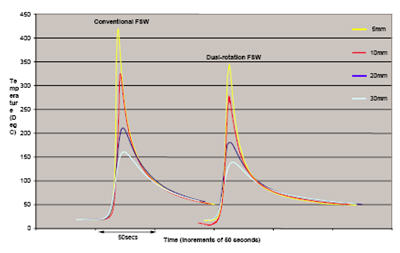
Figure 6: Thermal profiles of conventional rotary friction stir welds and dual-rotation friction stir welds made in 6.35 mm AA7050-T7451, using the same probe geometry and a travel speed of 5.25 mm/sec (315 mm/min). The probe rotation speed was 394 rev/min and 388 rev/min for conventional rotary and dual-rotation stir welding techniques respectively.
The lower temperatures reached in the dual rotary weld reduce the change in mechanical properties produced during friction stir welding. After two months natural ageing (Figures 7 & 8), the dual-rotation friction stir weld shows higher hardness values in the stirred zone, TMAZ and HAZ compared to the conventional friction stir weld. This indicates that the lower temperatures produced by the dual-rotation technique reduced thermal softening resulting in an increase in weld hardness.
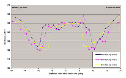
Figure 7: Hardness traverses as a function of depth through the cross section of a conventional friction stir weld made in 6.35 mm AA7050-T7451, using a travel speed of 5.25 mm/sec (315 mm/min) and a probe rotation speed of 394 rev/min.
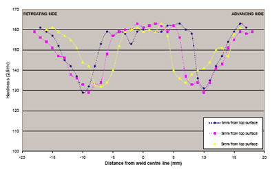
Figure 8: Hardness travers as a function of depth through the cross section of a dual-totary friction stir weld made in 6.35 mm AA7050-T7451, using the same probe geometry used the conventional friction stir weld (see fig.7), a travel speed of 5.25 mm/sec (315 mm/min), and a probe rotation speed of 388 rev/min and a shoulder rotational speed of 145 rev/min.
The heat affected zone (HAZ) of conventional friction stir welds in both 2xxx and 7xxx series aluminium alloys has been shown to be the region most susceptible to localized corrosive attack. Figure 9 shows a comparison of the extent of corrosion in specimens from conventional and dual-rotation friction stir welds that were exposed to the same test. These tests were carried out after two months natural ageing the 'near shoulder side' of the weld surface was removed and the surface prepared to a 1 micron finish before being immersed in a 0.1M NaCl aerated solution at ambient temperature for 7 days. Both welds were made in 6.35 mm AA7050-T7451 using the same probe geometry and a travel speed of 9.2 mm/secs (522 mm/min).
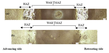
Figure 9: Photomacrograph of the top surface of (a) conventional friction stir weld and (b) Dual rotation friction stir weld.
The probe rotation speed was 394 rev/min and 388 rev/min for conventional rotary and Dual-rotation stir welding techniques respectively. A shoulder rotational speed of 145 rev/min was used for dual/rotation.
In the conventional friction stir weld the high temperature HAZ is shiny due to severe localized attack that has occurred in this region, therefore cathodically protecting the surrounding areas in the HAZ. In the dual-rotation friction stir weld there is no shiny region evident in the HAZ suggesting the degree of localized attack occurring in this region to be lower than in conventional friction stir welding.
立即查看数万种焊接材料!
Total Materia Horizon 包含数万种适用于焊接和电极制造的材料,包括材料基础性能及焊接条件下的性能数据。
申请 Total Materia Horizon免费试用帐户,加入来自全球 120 多个国家超过 500,000 名用户的大家庭。