Hydro-forming Process of Steel: Part Two
Abstract
The Tube Hydroforming (THF) process is a relatively new manufacturing technology, which has been used in the past decade. THF offers potential alternatives in the use of lightweight materials and hence can have a great impact in saving energy in the automotive industry.
THF offers several advantages as compared to conventional manufacturing via stamping and welding.
The Tube Hydroforming (THF) process is a relatively new manufacturing technology, which has been used in the past decade. THF offers potential alternatives in the use of lightweight materials and hence can have a great impact in saving energy in the automotive industry. Furthermore, THF also offers potential in design of structures with high stiffness. THF offers several advantages as compared to conventional manufacturing via stamping and welding. These advantages include: (a) part consolidation, for example stamped and welded sections to form a box section, can be formed as one single piece from a tubular material using hydroforming, (b) weight reduction through more efficient section design and tailoring of the wall thickness in structural components, (c) improved structural strength and stiffness via optimized section geometry, (d) lower tooling costs due to fewer parts, (e) fewer secondary operations (less welding and punching of holes during hydroforming), and (f) tighter tolerances and reduced springback that facilitates assembly, and finally (g) reduced scrap since trimming of excess material is far less in tube hydroforming than in stamping.
Figure 1 shows the six steps of the hydro-forming process:
A. Placement of the blank
B. Close the shape die around the circumference
C. Fill interior with liquid
D. Close the axial portion of the die
E. Compress the part
F. Evacuate the liquid and remove the part.
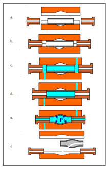
Figure 1: Tubular Hydroforming Process Steeps
Figure 2 illustrates some of the automotive components produced by THF process.
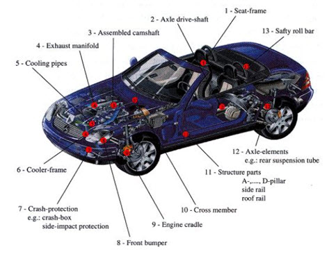
Figure 2: Examples of the automotive parts manufactured by tube hydroforming process
One of the leading automotive companies using hydroforming is BMW. In the newest models of BMW (e.g. BMW M3) hydroformed exhaust components are used (Figure 3).
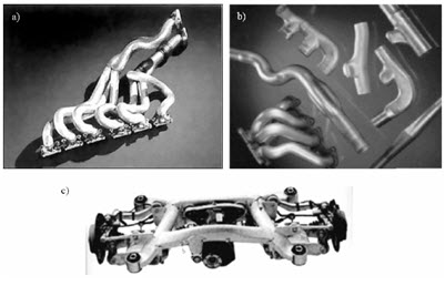
Figure 3: Exhaust system of BMW M3 (a) and its elements formed by hydroforming (b) as well as BMW rear axles with hydroformed components (c)
In most of the tube hydroforming processes, the decrease in wall thickness is prevented by compressing the tube in the axial direction simultaneously with the action of the internal pressure. If the internal pressure is too small, the axial compression causes wrinkling of the tube wall. Hence the paths of internal pressure and axial compression in the tube hydroforming are keys to prevent the occurrence of these defects. Finite element simulation has been employed to determine the pressure paths. A pulsating hydroforming process of tubes has been developed for the forming of hollow products with a complex shape. An improvement of the formability by means of pulsating hydroforming have been investigated and simulated by the finite element method.
Bellows are quite an important group of products made by the hydroforming of tubes, Figure 4. They are commonly used in piping systems to absorb expansion and mechanical movement and they have widespread applications in industrial and chemical plants, power systems, heat exchangers, and automotive vehicle parts. Special stands for expanding the tube wall by internal pressure and axial compression of the tube in order to produce bellows were developed in the Metal Forming Department at Warsaw University of Technology in 1960s, where they produced bellows with one and multi-layer walls.
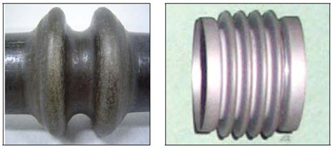
Figure 4: The hydroformed bellows
鍛造材料の特性を即座に検索!
Total Materia Horizon には、鍛造に適した数千種類の材料の機械的・物理的特性、応力-ひずみ曲線、熱間鍛造用高温データなどが収録されています。
Total Materia Horizonの無料テストアカウントを開設して、120カ国以上、50万人を超えるユーザーのコミュニティに参加しましょう!