Fatigue crack growth
Abstract
Fatigue crack growth prediction has become critical in aerospace engineering, driving the development of safe-life and fail-safe design approaches. The aircraft industry pioneered methods to understand crack propagation behavior, enabling components with existing cracks to remain in service through calculated inspection intervals. By applying fracture mechanics principles and understanding material growth rate characteristics, engineers can predict the number of cycles required for crack growth to specified lengths or final failure. The Paris equation provides the foundation for fatigue life calculations in Region II of the crack growth curve, where most structural applications operate. This approach significantly extends component service life while maintaining safety through regular inspections and mathematical modeling of crack propagation rates.
Introduction to Fatigue Crack Growth in Aerospace Engineering
The aerospace industry has spearheaded efforts to understand and predict fatigue crack growth, recognizing that the majority of a component's fatigue life may be consumed during crack propagation phases. This understanding has led to revolutionary design philosophies that fundamentally changed how engineers approach structural integrity and maintenance in aircraft applications.
The development of safe-life and fail-safe design approaches represents a paradigm shift in aerospace engineering. Rather than requiring components to remain crack-free throughout their service life, these methodologies acknowledge that cracks will inevitably form and focus on controlling their growth behavior. This approach enables engineers to design components that can operate safely even with existing cracks, provided the cracks do not grow to critical sizes between specified inspection intervals.
By combining knowledge of material growth rate characteristics with regular inspection protocols, cracked components can be maintained in service for extended periods. This concept not only improves economic efficiency but also enhances safety through predictive maintenance strategies based on scientific understanding of crack behavior.
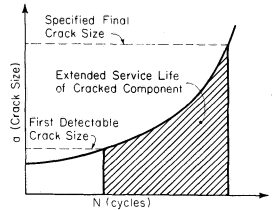
Figure 1: Extended service life of a cracked component, illustrating the safe-life design concept
Fatigue Crack Growth Curves and Data Analysis
Understanding crack propagation behavior requires systematic analysis of crack growth data under controlled conditions. Typical constant amplitude crack propagation experiments generate data that reveal fundamental relationships between crack length, applied cycles, and growth rates.
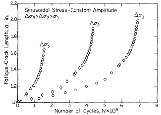
Figure 2: Constant amplitude crack growth data showing crack length (a) plotted versus number of cycles (N)
The data demonstrates that most of a component's operational life occurs while the crack length remains relatively small. This observation has profound implications for maintenance scheduling and inspection protocols. Additionally, crack growth rates increase significantly with increased applied stress, establishing the critical relationship between loading conditions and crack propagation behavior.
The crack growth rate, expressed as da/dN, is obtained by calculating the derivative of the crack length versus cycles curve. Two widely accepted numerical approaches for obtaining this derivative are the spline fitting method and the incremental polynomial method. These computational techniques enable engineers to extract precise growth rate information from experimental data, forming the foundation for predictive models.
Values of log da/dN can be plotted versus log ΔK for any given crack length using the fundamental relationship:
ΔK = Δσ√(πa)f(g) (1)
where Δσ represents the remote stress range applied to the component.
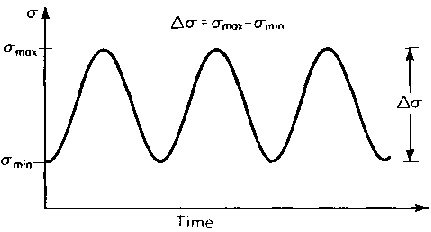
Figure 3: Remote stress range diagram illustrating the stress application in fatigue testing
Three-Region Crack Growth Behavior
The relationship between log da/dN and log ΔK produces a characteristic sigmoidal curve that can be divided into three distinct regions, each representing different crack growth mechanisms and practical applications.
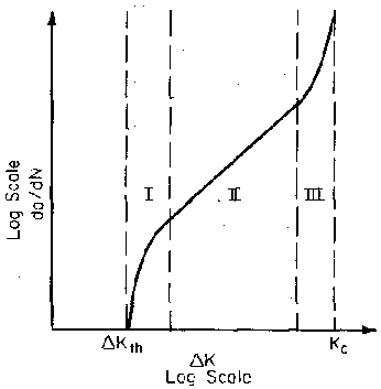
Figure 4: Three regions of crack growth rate curve showing the complete sigmoidal relationship
Region I: occurs at low stress intensities where cracking behavior is dominated by threshold effects, specifically ΔKth. In this region, crack growth rates are extremely low, and cracks may effectively remain dormant under certain loading conditions.
Region II: represents the mid-range where the curve exhibits essentially linear behavior on the log-log plot. Most structural applications operate within this region, making it the most practically important for engineering design.
Region III: encompasses high ΔK values where crack growth rates become extremely high and little fatigue life remains. This region typically occurs near final failure and represents unstable crack growth conditions.
Region II Analysis and the Paris Equation
Most current applications of Linear Elastic Fracture Mechanics (LEFM) concepts for describing crack growth behavior focus on Region II analysis. Within this region, the slope of the log da/dN versus log ΔK curve remains approximately linear, with growth rates typically ranging between 10⁻⁶ and 10⁻³ inches per cycle.
Numerous mathematical relationships have been proposed to describe Region II behavior, but the Paris equation, introduced in the early 1960s, has achieved the widest acceptance in engineering practice. The Paris equation states:
da/dN = C(ΔK)ᵐ (2)
where C and m represent material constants, and ΔK is the stress intensity range calculated as Kmax - Kmin.
The exponent m typically ranges between 3 and 4 for most engineering materials, with observed values spanning from 2.3 to 6.7 and a statistical average of approximately 3.5. These material constants can be determined through standardized testing procedures, with ASTM E647 providing comprehensive guidelines for fatigue crack growth testing protocols.
Fatigue Life Calculations and Practical Applications
The crack growth life, expressed in cycles to failure, can be calculated using the Paris equation through integration techniques. The general relationship for cycles to failure is expressed as:
Nf= ∫[from ai to af] da/[C(ΔK)ᵐ] (3)
where ai represents the initial crack length and af represents the final (critical) crack length at failure.
Substituting the Paris formulation yields:
Nf = (1/C) ∫[from ai to af] da/(ΔK)ᵐ (4)
The complexity of this integration depends on how the stress intensity factor ΔK varies with crack length and the correction factor f(g). For many practical applications, numerical integration methods are required due to the crack length dependence of these parameters. However, as a first approximation, the correction factor can be calculated at the initial crack length, allowing closed-form evaluation of the integral.
Closed-Form Integration Example
Fatigue life calculations for specific geometries can often be solved analytically when the correction factor remains constant. Consider a small edge crack in a large plate where the correction factor f(g) does not vary significantly with crack length. The stress intensity factor range becomes:
ΔK = 1.12Δσ√(πa) (5)
Substituting this into the Paris equation produces:
da/dN = C[1.12Δσ√(πa)]ᵐ (6)
Separating variables and integrating for m ≠ 2 yields:
Nf= (2/[(m-2)C(1.12Δσ)ᵐπᵐ/²]) [ai^((2-m)/2) - af^((2-m)/2)] (7)
Before solving this equation, the final crack size af must be determined using fracture toughness criteria:
af = (1/π) × (KIC/1.12σmax)² (8)
For more complex formulations where the correction factor varies with crack length, iterative computational procedures may be required to solve for af accurately.
Critical Factors in Fatigue Life Estimation
Understanding the sensitivity of fatigue life estimation to various parameters is crucial for reliable engineering predictions. The fatigue life calculation shows strong dependence on the initial crack length ai, but generally exhibits low sensitivity to the final crack length af when ai << af . This relationship has important practical implications for inspection strategies and design margins.
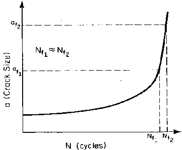
Figure 5: Effect of final crack size on life, demonstrating the relative insensitivity of fatigue life to final crack size
Large changes in af result in relatively small changes in predicted fatigue life Nf, as demonstrated through parametric studies. This characteristic provides some margin of safety in practical applications, as uncertainties in critical crack length determination have minimal impact on life predictions compared to uncertainties in initial crack size detection.
The practical significance of this relationship emphasizes the importance of early crack detection methods and accurate initial crack size assessment in fatigue life management programs. Advanced non-destructive evaluation techniques continue to improve the precision of initial crack size determination, directly improving the reliability of fatigue life predictions.
Implications for Aerospace Design and Maintenance
The application of fracture mechanics principles to fatigue crack growth has revolutionized aerospace design and maintenance philosophies. Rather than designing components to remain crack-free, engineers can now develop maintenance schedules based on scientific understanding of crack growth behavior. This approach enables more efficient use of materials and extends component service lives while maintaining safety margins through calculated inspection intervals.
Modern aerospace maintenance programs integrate fatigue crack growth predictions with advanced inspection technologies to optimize both safety and economic efficiency. The combination of theoretical understanding, computational capabilities, and practical testing methods continues to advance the field of fatigue crack growth analysis, supporting the development of increasingly sophisticated and reliable aerospace structures.
Accédez immédiatement à des centaines de propriétés cycliques des matériaux !
Total Materia Horizon inclut une collection unique de données en fatigue pour les métaux et les non-métaux, tant oligocyclique que polycyclique.
Profitez d’un compte d’évaluation GRATUIT sur Total Materia Horizon et rejoignez notre communauté qui compte plus de 500.000 utilisateurs dans plus de 120 pays.