Critical Crack Tip Opening Displacement (CTOD) Testing: Part Two
Abstract
Crack tip opening displacement (CTOD) testing serves as a critical method for evaluating fracture toughness in engineering applications, providing comprehensive coverage of all fracture behaviors between stress intensity factor K and J-integral test extremes. This article examines research findings on CTOD testing of high-strength low-alloy (HSLA) steels including HT50, HT80, and mild steel grades. The analysis covers mechanical property evaluations, fracture assessment methodologies using British Standard BS7910, and failure assessment diagram (FAD) applications. Results demonstrate that CTOD values vary significantly based on crack orientation, with specimens showing maximum toughness in width direction and minimum values in thickness direction due to microstructural variations and inclusion effects.
Introduction to CTOD Testing Applications
Crack tip opening displacement testing represents a widely applied engineering method that provides comprehensive fracture behavior analysis. The CTOD method stands uniquely as the only standardized test covering the complete spectrum of fracture behaviors occurring between extremes associated with stress intensity factor K and J-integral testing approaches.
Comparative Analysis of Steel Grades Using CTOD Methods
Research conducted by Z. Praunseis and P. Virtič involved comprehensive testing of three distinct steel types to compare their mechanical properties. The investigation focused on HSLA steel grades HT50 and HT80 alongside mild steel, utilizing standard tensile testing, Charpy impact testing, and CTOD evaluation methods. Specimens were systematically extracted from steel plates in rolling, thickness, and width directions to ensure comprehensive directional property assessment.
The CTOD fracture toughness evaluation employed standard static testing protocols with specimens loaded at a constant crosshead speed of 0.5 mm/min. Testing occurred at -10°C following recommendations from the Offshore Mechanics and Arctic Engineering (OMAE) association. Researchers utilized the single specimen method with standard fracture mechanics tensile specimens featuring shallow notches.

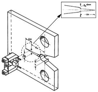
Figure 1: Direct measurement of CTOD values at crack tip of fracture mechanics specimen
CTOD Testing Methodology and Measurement Techniques
All test specimens underwent fatigue pre-cracking using the Step-Wise High R ratio (SHR) method procedure. During CTOD testing, researchers employed potential drop technique for monitoring stable crack growth progression. Direct CTOD value measurements utilized specialized clip gauges positioned on specimen side surfaces at the fatigue crack tip over a 5 mm gauge length.
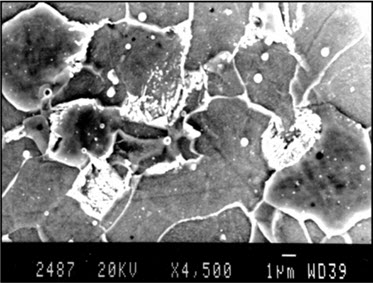
The directly measured CTOD fracture toughness values revealed significant variations across different steel types and orientations. Maximum CTOD toughness occurred in specimens with crack tips located in the width direction (C orientation). Conversely, specimens with crack tips positioned in the thickness direction (B orientation) demonstrated the lowest CTOD values due to brittle fracture occurrence in the predominantly ferritic microstructure containing carbides (Fe3C) precipitated at grain boundaries.
Table 1: Mechanical properties of HSLA steel HT80 and HT50 and mild steel plate in the rolling direction (A), thickness direction (B) and width direction (C)
| Steel grade | Measured direction | Yield strain (MPa) | Tensile strain (MPa) | CTOD (mm) | Charpy V (J) at -10°C |
| HT50 | A | 542 | 591 | 0.390 | 47, 68, 71 Av=62 |
| HT80 | A | 693 | 830 | 0.401 | 69, 78, 64 Av=70 |
| Mild steel | A | 452 | 497 | 0.423 | 42, 55, 62 Av=53 |
| HT50 | B | 501 | 562 | 0.240 | 39, 41, 55 Av=45 |
| HT80 | B | 657 | 799 | 0.253 | 53, 68, 66 Av=62 |
| Mild steel | B | 439 | 471 | 0.231 | 39, 44, 61 Av=48 |
| HT50 | C | 531 | 587 | 0.416 | 42, 76, 69 Av=62 |
| HT80 | C | 665 | 811 | 0.478 | 67, 71, 63 Av=67 |
| Mild steel | C | 447 | 478 | 0.443 | 40, 51, 65 Av=52 |
Microstructural Analysis and Fracture Initiation Points
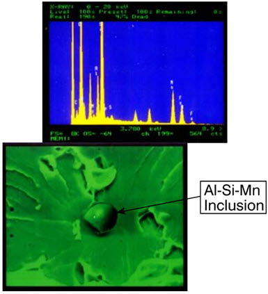
Critical analysis revealed that brittle fracture initiation points primarily consisted of Al-Si-Mn inclusions.

Figure 2: Mainly ferritic microstructure with carbides (Fe3C) precipitated at the grain boundary

Figure 3: Appearance and EDX analysis of brittle fracture initiation point, i.e. Al-Si-Mn inclusion
Proper identification of these brittle fracture initiation points requires Energy Dispersive X-ray (EDX) analysis application to both fracture surfaces. Without comprehensive EDX analysis of both surfaces, researchers risk detecting fictitious brittle fracture initiation points, leading to inaccurate conclusions.
CTOD Assessment Standards and Welding Applications
The CTOD method serves as an essential criterion for welding toughness assessment, gaining popularity in general engineering applications as structural thickness requirements increase. Different standards establish acceptable CTOD values to ensure structural safety and stability maintenance.
Research by Z. Xia and colleagues demonstrated that single edge fatigue pre-crack CTOD specimens can be assessed as flaws using British Standard 7910-2005 technical approaches. This standard, titled "Guide to methods for assessing the acceptability of flaws in metallic structures," provided assessment frameworks for EQ70/56 welded joints, confirming that measured CTOD values fell within acceptable ranges.
Failure Assessment Diagram (FAD) Applications
British Standard BS7910 utilizes fracture mechanics principles to fulfill assessments through Failure Assessment Diagrams (FAD), comparing structural crack resistance against actual crack loading capabilities. The standard evolved from BS7910:1999 to BS7910:2005, incorporating three assessment levels for metallic structure flaws based on materials involved, available input data, and required conservatism levels.
BS7910 addresses various flaw types including planar flaws, non-planar flaws, and shape imperfections. For high-strength heavy steel plate assessment, CTOD test specimens receive pre-carved cracks throughout their thickness, with welding seam centers determined using Level 2B assessment protocols.
Level 2B FAD Assessment Procedures
Level 2B FAD assessment utilizes fracture toughness as an assessment index, represented as Kr (stress intensity factor ratio) or √δr (square root of CTOD fracture ratio). CTOD testing treats single edge running cracks as flaws assessed by FAD, plotting fracture ratios as ordinates against load ratios (Sr) as abscissa values.
Level 2 assessment employs specific assessment curves defined by mathematical equations and cut-off values. Assessment points falling within areas bounded by axes and assessment curves indicate acceptable flaws, while points on or outside curves represent unacceptable conditions.
CTOD Toughness Assessment Protocol for High-Strength Steel
The comprehensive CTOD toughness assessment methodology for heat affected zones and welding seam centers in high-strength thick steel involves systematic procedures. Initial steps require measuring CTOD values of welding joints at specific temperatures, followed by plotting stress-strain curves through uniaxial tensile testing and converting them to true stress-strain curves using established equations.
Subsequent procedures involve plotting Level 2B FAD using true stress-strain curves to conduct failure assessments of joints and welding seam centers. Final calculations determine load ratios and fracture ratios representing assessment point coordinates using CTOD values and stress-strain curve data, completing toughness assessments through FAD plotting.
Research Conclusions and Practical Applications
Z. Xia and colleagues concluded that average critical CTOD values measured 0.06 mm based on their comprehensive analysis. Their detailed calculations suggest that acceptable CTOD values for heavy plates could be appropriately modified and lowered compared to current standard specifications, providing more realistic assessment criteria for practical applications.
These findings contribute significantly to understanding CTOD testing applications in modern engineering, particularly for high-strength steel welding applications where structural integrity remains paramount for safety and performance requirements
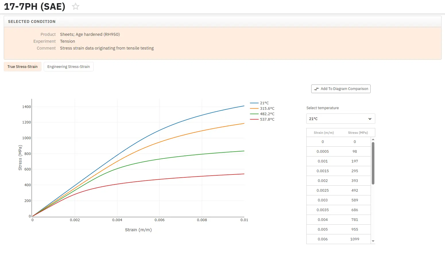
Accédez immédiatement à des centaines de courbes contrainte-déformation !
Total Materia Horizon inclut une collection unique de courbes de traction/compression pour les métaux et les non-métaux. Les courbes conventionnelles et rationnelles sont disponibles, à diverses vitesses de déformation, conditions métallurgiques et températures le cas échéant.

Profitez d’un compte d’évaluation GRATUIT sur Total Materia Horizon et rejoignez notre communauté qui compte plus de 500.000 utilisateurs dans plus de 120 pays.