Friction Stir Welding: Part Two
Abstract
The skew-stir™ technique provides an easier material flow path than conventional FSW and a weld nugget region of width greater than the diameter of the probe. In addition the skew action provides an orbital forging action at the root of the weld, which improves weld quality in this region.
The use of the Re-stir™ welding technique provides a cyclic and essentially symmetrical welding and processing treatment. Most problems associated with the inherent asymmetry of conventional rotary FSW are avoided.
TWI Ltd, Cambridge, United Kingdom
The skew-stir™ technique provides an easier material flow path than conventional FSW and a weld nugget region of width greater than the diameter of the probe. In addition the skew action provides an orbital forging action at the root of the weld, which improves weld quality in this region.
Work has been undertaken to establish the fatigue performance of welds made using the skew-stir™ technique and a fatigue-tested sample is shown in Figure 1.
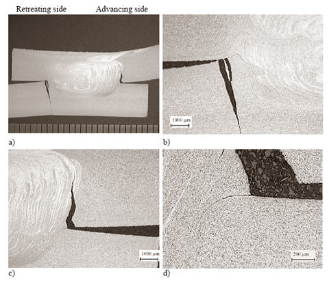
Figure 1: Lap weld made with the retreating side near the top sheet edge (RNE configuration) using Skew-stir™ with A - skew™ probe (8.25 mm in length) in 6 mm thick 5083-H111 aluminum alloy at a welding speed of 3 mm.sec (180 mm/min)
a) Macrosection
b) Detail of fracture, bottom sheet retreating side
c) Detail of fracture top sheet advancing side
d) Detail of the form of the notch at the edge of the weld-advancing side.
Typically these Skew-stir™ lap welds gave good fatigue performance when compared with an artificial weld made from parent material of similar geometry as shown in Figure 2.
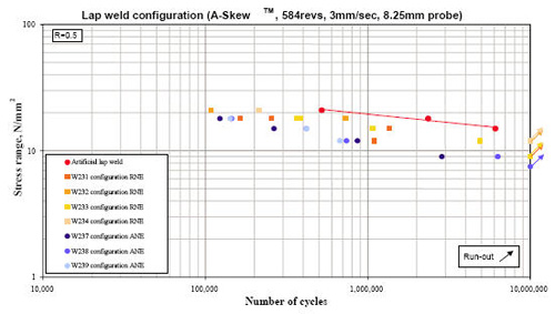
Figure 2: Fatigue results of welds carried out with different lap configurations with a 8.25 mm long probe.
Reversal Stir Welding –Re-stir™
The following describes preliminary studies being carried out on Re-stir™ welding at TWI. The salient features of the Re-stir™ welding technique are illustrated in Fig.3. This illustration applies to both angular reciprocating, where reversal is imposed within one revolution, and rotary reversal, where reversal is imposed after one or more revolutions.
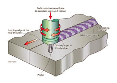
Figure 3: The basic principle of Re-stir™, showing the reversal technique.
The use of the Re-stir™ welding technique provides a cyclic and essentially symmetrical welding and processing treatment. Most problems associated with the inherent asymmetry of conventional rotary FSW are avoided.
Figure 4 shows the detail of the surface of weld made at 4 mm/sec (240 mm/min) travel speed, using 10 revolutions per interval. The fine surface ripples reveal the number of rotations and the extent of the interval, while the less frequent, coarser and wider surface ripples reveal the position of the change in rotation direction. For Re-stir™, the distance and time between each interval depends on the combination of rotational speed and the travel speed used.
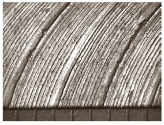
Figure 4: Close up of Re-stir weld surface formed beneath the tool shoulder showing surface rippling and reversal interval. Produced at 4 mm/sec (240 mm/min) welding travel speed, using 10 revolutions per interval.
Macrosections of a lap weld made by Re-stir™ are shown in Figure 5 a, b & c. This weld was made in 5083-H111 condition aluminium alloy, using a Flared-Triflute™ type probe designed for rotary stir, at a travel speed of 3.3 mm/sec (198 mm/min) using 10 revolutions per interval. The plan view in Figure 4c reveals a patterned weld region surrounded by a HAZ. There is some evidence that during the reversal stage some of the "Third-body" plasticized material close to the probe is "re-stirred" back in the opposite direction.
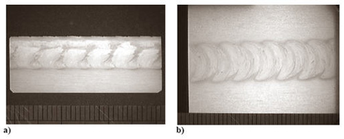
Figure 5: Metallurgical sections showing the effect of the Re-stir technique on the weld shape, produced at a welding speed of 3.3 mm/sec (198 mm/min), using 10 revolutions per interval.
a) Longitudinal macrosection showing regular patterns caused by rotation reversal
b) Plan macrosection taken mid thickness showing the effect of reversal motion.
The Re-stir™ process requires further optimization to achieve welds of reproducibly high quality and freedom from defects but early trials suggest benefits in terms of weld symmetry. Initial work using an A-skew probe also suggests that it may be possible to achieve a slight down turn in the overlapping plate/weld interface at the outer regions of the weld which may be beneficial in particular structures and loading situations. Figure 6 a, b & c, illustrates this effect in an overlap weld in 5083-H111 condition aluminium alloy.
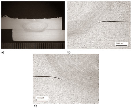
Figure 6: Detail of the outer regions of a Re-stir weld made with an A-skew probe in combination with a skew motion, at a travel speed of 1.6 mm/sec (96 mm/min), using 8 revolutions per reversal interval.
a) Macrosection
b) Detail of notch (that would formerly have been at the retraiting side with conventional rotary FSW)
c) Detail of notch (that would formerly have been at the advancing side with conventional rotary FSW).
Typically these Re-stir™ lap welds gave very good fatigue performance when compared with an artificial weld made from parent material of similar geometry as shown in Fig. 7.
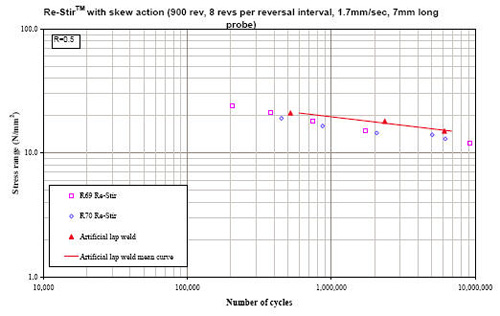
Figure 7: Fatigue results of welds carried out with reversal motion Skew-stir™.
¡Encuentre al Instante Miles de Materiales de Soldadura!
Total Materia Horizon contiene miles de materiales aptos para soldadura y electrodos, con sus propiedades tanto a granel como en condiciones soldadas.
Obtenga una cuenta de prueba GRATUITA de Total Materia Horizon y únase a nuestra comunidad que traspasa los 500.000 usuarios provenientes de más de 120 países.