Residual Welding Stresses
Residual welding stresses are a key parameter which needs to be controlled in order to minimize failures at the weld site.
The three main observed sources of stress are contraction stress, stress due to higher surface cooling and stress due to phase transformation.
Welding is one of the most important technological processes used in many branches of industry such as industrial engineering, shipbuilding, pipeline fabrication among others. Residual stresses arising after welding exert a considerable influence on the service characteristics of welded equipment and their control allows it possible to avoid failure of the welded joint.
Different techniques are used to control the stress state in the weld region. X-ray diffraction technique is one of the methods widely used to analyze residual stress distribution in the weld seam and near the welded region. However, numerous measurements by X-ray tensometry contain contradictory information about weld-induced residual stresses and the analysis of stress distribution is usually carried out without considering of equilibrium conditions.
Tensile residual stresses may reduce the performance or cause failure of manufactured products. They may increase the rate of damage by fatigue, creep or environmental degradation. They may reduce the load capacity by contributing to failure by brittle fracture, or cause other forms of damage such as shape change or crazing. Compressive residual stresses are generally beneficial, but cause a decrease in the buckling load.
Residual stresses may be measured by non-destructive techniques, including X-ray diffraction, neutron diffraction and optic magnetic and ultrasonic methods; by locally destructive techniques, including hole drilling and the ring core and deep hole methods; and by sectioning methods including block removal, splitting, slicing, layering and the contour method. The selection of the optimum measurement technique should take account of volumetric resolution, material, geometry and access.
Prediction of residual stresses by numerical modelling of welding and other manufacturing processes has increased rapidly in recent years. Modelling of welding is technically and computationally demanding, and simplification and idealization of the material behavior, process parameters and geometry is inevitable. Numerical modelling is a powerful tool for residual stress prediction, but validation with reference to experimental results is essential.
Sources of residual stress
Residual stress in welds is produced by localized metal tensions occurring immediately after welding, which are:
a) Contraction stress. This is the main source of residual stress. It takes place during the cooling of the welded areas, which have undergone non uniform heating.
b) Stress due to higher surface cooling. When a weld cools down the surface cools faster than the inside, even if this cooling occurs in still air. The greater the thickness, the more stress is generated.
c) Stress due to phase transformation. It occurs due to the transformation of austenite (face centered cube, fcc) to ferrite (body centered cube, bcc), that causes an increase in volume to which the base metal is opposed.
There are various ways of measuring or estimating residual stresses, the direct measurements can be either semi destructive (e.g., hole drilling and indenting or nondestructive (x-ray (laboratory or synchrotron) or neutron diffraction (ND) and ultrasonic). Finite element approaches have been used for welding but a major review still determined that there remains an “urgent need” to develop the required knowledge. The residual stresses in weld repairs are much more complex and difficult to understand and predict presumably because of the small size of such welds and the high restraint involved.
In the work of A.M.Paradowsa et al.have reported experimental ND measurements of weld stresses generated by single-bead-on-plate. The focus was on the value of line scans of the stress (strain) variation on a plane through the middle of the weldment. The parent material used in this study was a low-carbon steel. The chemical composition of the material and weld metal are shown in Table 1. The typical mechanical properties of parent and weld metal are shown in Table 2.
Welding procedure
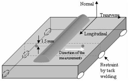
Experimental work was carried out on three specimens. All the samples were fully restrained single bead-on-plate. The restraint was achieved by tack welding the sample (Figure 1) to a very thick steel plate which was cut off after cooling down to the room temperature.
The welds were produced using a flux-cored arc welding (FCAW) process. The specimens were mounted under an automatic-speed controlled welding torch. The welding parameters are shown in Table 3. Table 4 shows the weld geometrical parameters. There was no pre- or post- weld heat (PWHT) treatment.
Transverse sections were taken across the welds in the middle of the plate for all samples.

Figure 1: Illustration of fully restrained single bead-on-plate, showing the direction of the measurements (transverse x, normal y, longitudinal z) using neutron diffraction

Table 1: Chemical composition of the consumable materials (in wt.%)

Table 2: Typical mechanical properties

Table 3: Parameters used in the experimental work

Table 4: Typical mechanical properties
Results
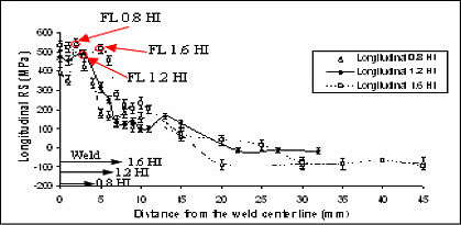
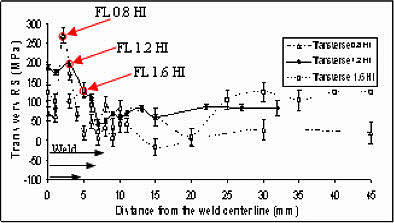
The residual stresses were derived from the elastic strain measurements using a Young’s modulus of 207 GPa, and Poisson’s ratio of 0.3. The results for longitudinal and transverse residual stress components for all three samples are shown in Figures 2 and 3. Error bars are based on the uncertainties in the values of the peak diffraction angle.

Figure 2: Longitudinal residual stresses measured by ND against distance from the weld center line. Error bars based on uncertainty in the value of the peak diffraction angle are shown

Figure 3: Transverse residual stresses
The peak stress in the weld (which is in the longitudinal direction) is significantly higher in the weld area in all samples (Figures 2 and 3), than the specified yield stress of the parent metal in question (250 MPa). They are also higher than the yield stresses of the weld metal (Table 2). It must be noted from the stress plots that there is significant hydrostatic tension in the fused zone (100–200 MPa) which means that the maximum principal stresses in longitudinal direction can be higher than yield (reflecting the fact that deviatoric stesses are required to create yield conditions).
The peak stress in these cases does not occur under the toe of the weld but in the middle of weld or at the FL. In the transverse direction maximum residual stress of around half of the maximum value of longitudinal stress has been observed at the FL, decreasing in the value with the increasing heat input.
One possible explanation is the especially high quench speeds associated with the fusion line, where the liquid metal is in direct contact with the parent metal. The full exploitation of this kind of information is one key issue in future studies. Theirs work is currently developed methods of cross checking these results with finite element modelling of the welding process.
Total Materia
A Total Materia é a principal plataforma de informações sobre materiais, fornecendo as informações mais abrangentes sobre propriedades de materiais metálicos e não metálicos e outros registros de materiais.
Todas essas informações estão disponíveis na Total Materia Horizon, a mais moderna ferramenta de seleção e informações sobre materiais, que oferece acesso inigualável a mais de 540.000 materiais, bem como a dados de referência selecionados e atualizados.
O Total Materia Horizon inclui:
- Dados abrangentes sobre propriedades mecânicas e físicas
- >80 padrões globais e suas equivalências
- Ferramentas de precisão para comparação e análise que simplificam o processo de seleção.
- Dados de tensão-deformação, conformabilidade, fadiga, fluência e fratura
- Exportação para mais de 25 formatos CAx.
- Informações sobre tratamento térmico, metalografia e corrosão
- Dados de soldagem, brasagem e adesivos
- Fontes rastreáveis e atualizadas mensalmente garantem a confiabilidade