Quench hardening of steel
Abstract
Quench hardening is a critical heat treatment process for steel that involves heating to austenitic temperature followed by rapid cooling to produce martensite. This article examines the parameters affecting successful hardening, including temperature control, soaking times, and quenching media selection. It explains the metallurgical transformations during quenching and subsequent tempering processes that optimize hardness, strength, and toughness. Special attention is given to microstructural changes, carbon content effects, design considerations for minimizing quench cracking, and the fundamental mechanisms underlying the heat treatment of steel alloys.
Introduction to Quench Hardening
Hardening of steel is obtained by a suitable quench from within or above the critical range. The temperatures are the same as those given for full annealing. The soaking time in air furnaces should be 1.2 minutes for each millimeter of cross-section or 0.6 minutes in salt or lead baths. Uneven heating, overheating, and excessive scaling should be avoided.
The quenching process is necessary to suppress the normal breakdown of austenite into ferrite and cementite, and to cause a partial decomposition at such a low temperature to produce martensite. To achieve this, steel requires a critical cooling velocity, which is greatly reduced by the presence of alloying elements, which therefore enable hardening with milder quenching media (such as oil in alloy and hardening steels).
Carbon Content and Hardening Effectiveness
Steels with less than 0.3% carbon cannot be hardened effectively, while the maximum effect is obtained at approximately 0.7% carbon. This limitation occurs due to an increased tendency to retain austenite in high carbon steels, as illustrated in Figure 1.
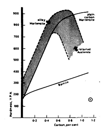
Figure 1: Variation of hardness of martensite and bainite with carbon content
Quenching Media and Techniques
Water is one of the most efficient quenching media where maximum hardness is required, but it can cause distortion and cracking of the workpiece. When some hardness can be sacrificed for better dimensional control, whale oil, cotton seed oil, and mineral oils are used. These oils tend to oxidize and form sludge over time, resulting in reduced quenching efficiency.
The quenching velocity of oil is significantly lower than that of water. Even in small sections, ferrite and troostite formation may occur during oil quenching. Intermediate cooling rates between water and oil can be achieved with water containing 10-30% Ucon, a substance with inverse solubility that deposits on the object to reduce the cooling rate.
To minimize distortion during quenching:
- Long cylindrical objects should be quenched vertically
- Flat sections should enter the bath edgewise
- Thick sections should enter the bath first
To prevent steam bubbles from forming soft spots, water quenching baths should be agitated. Fully hardened and tempered steels develop the best combination of strength and notch-ductility.
Tempering and Toughening Processes
The martensite structure in quenched tool steel is exceedingly brittle and highly stressed. Consequently, cracking and distortion are likely to occur after quenching. Retained austenite is unstable, and as it transforms, dimensions may alter—dies, for example, may change by approximately 0.012 mm.
It is therefore necessary to warm the steel below the critical range to relieve stresses and allow the arrested reaction of cementite precipitation to proceed. This process is known as tempering.
Different tempering temperature ranges produce specific results:
150-250°C: The object is heated in an oil bath immediately after quenching to prevent cracking, relieve internal stress, and decompose austenite without significant softening.
200-450°C: Used to toughen the steel at the expense of hardness. This range typically produces a Brinell hardness of 350-450.
450-700°C: The precipitated cementite coalesces into larger masses, and the steel becomes softer. The resulting structure is known as sorbite, which at higher temperatures becomes coarsely spheroidized. It etches more slowly than troostite and has a Brinell hardness of 220-350. Sorbite is commonly found in heat-treated constructional steels such as axles, shafts, and crankshafts subjected to dynamic stresses. Quenching followed by tempering in this temperature range is frequently referred to as "toughening," and it produces an increased ratio of elastic limit to ultimate tensile strength.
Tempering reactions occur slowly. Both reaction time and heating temperature are important factors. Tempering is increasingly carried out under pyrometric control in oil, salt (e.g., equal parts sodium and potassium nitrates for 200-600°C), or lead baths, as well as in furnaces with circulating air. After tempering, objects may be cooled either rapidly or slowly, except for steels susceptible to temper brittleness.
Temper Colors and Applications
Temper colors formed on a cleaned surface are occasionally used as a guide to temperature. These colors exist due to interference effects of thin oxide films formed during tempering, similar to oil films on water. Alloy steels such as stainless steel form thinner films than carbon steels at a given temperature, producing colors lower in the sequence. For example, pale straw corresponds to 300°C in stainless steel instead of 230°C in carbon steel, as shown in Table 1.
Table 1. The table shows temper colors, corresponding temperatures in °C, and typical applications. This table should be positioned here in the final document.
| Temper Colour | Temperature °C | Objects |
| Pale straw | 230 | Planing and slotting tools |
| Dark straw | 240 | Milling cutters, drills |
| Brown | 250 | Taps, shear blades for metals |
| Brownish-purple | 260 | Punches, cups, snaps, twist drills, reamers |
| Purple | 270 | Press tools, axes |
| Dark purple | 280 | Cold chisels, setts for steel |
| Blue | 300 | Saws for wood, springs |
| Blue | 450–650 | Toughening for constructional steels |
For cutting tools such as turning, planing, shaping tools, and chisels, only the cutting parts typically require hardening. This is frequently accomplished in engineering workshops by heating the tool to 730°C, followed by quenching the cutting end vertically. After the cutting end cools, it is cleaned with a stone, and heat from the tool's shank is allowed to temper the cutting edge to the correct color. Then the entire tool is quenched. Oxidation can be reduced by coating the tool with a mixture of charcoal and oil.
Microstructural Changes During Tempering
The principles underlying the tempering of quenched steels closely resemble those of precipitation hardening. The overlapping changes that occur when high-carbon martensite is tempered are shown in Figure 2 and can be described in several stages:
Stage 1 (50-200°C)
Martensite breaks down to a transition precipitate known as ε-carbide (Fe2.4C) across twins and a low-carbon martensite. This results in slight dispersion hardening and decreases in volume and electrical resistance.
Stage 2 (205-305°C)
Decomposition of retained austenite to bainite occurs, leading to a decrease in hardness.
Stage 3 (250-500°C)
The aggregate of low-carbon martensite and ε-carbide converts into ferrite and cementite precipitated along twins. These precipitates gradually coarsen to form visible particles, causing rapid softening, as shown in Figure 3.
Stage 4 (400-700°C)
Carbide changes occur in alloy steels. In steels containing a single alloying element, cementite forms first, and the alloy diffuses to it. When sufficiently enriched, the Fe3C transforms to an alloy carbide. After further enrichment, this carbide may be replaced by another, and this formation of transition carbides may repeat several times before the equilibrium carbide forms. In chromium steel, the changes follow the sequence: Fe3C→Cr7C3→Cr23C6.
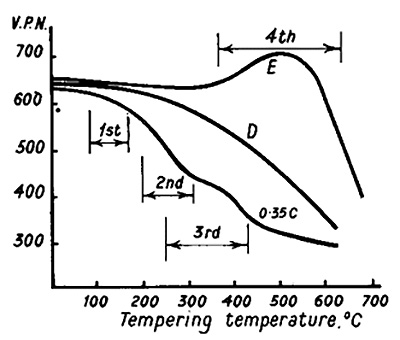
Figure 2.Tempering curves for 0,35 % C steel and die steel
In steels containing multiple carbide-forming elements, the reactions are often more complex, and the decomposing carbides are not necessarily followed by carbides based on the same alloying elements. The transformation can occur in situ through gradual exchange of atoms without appreciable hardening, or by dissolution of existing iron carbides and fresh nucleation of coherent carbide, producing considerable hardening that counteracts the normal tempering softening.
In some alloy steels, hardness remains constant up to approximately 500°C, or in some cases rises to a peak followed by a gradual decrease due to loss of coherence and coalescence of carbide particles. This age-hardening process, known as secondary hardening, enhances the high-temperature creep properties of steel (for example, steel E in Figure 2). Chromium appears to stabilize cementite particle size over the 200-500°C range. Vanadium and molybdenum form fine dispersions of coherent precipitates (V4C3Mo2C) in a ferrite matrix, producing considerable hardening. When over-aging begins, V4C3 grows at grain boundaries and forms a Widmanstätten pattern of plates within the grain.
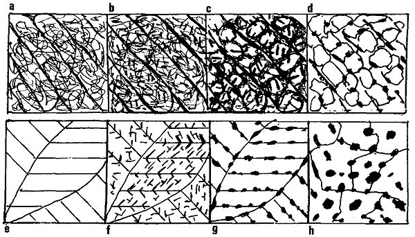
Figure 3: Microstructural images of martensitic structures at different tempering stages.
Figure 3 above shows the microstructural images of martensitic structures at eight different tempering stages, with more insights into each image provided below:
- As quenched. Laths with high density of dislocation
- Tempered 300°C. Widmanstätten precipitation of carbides within laths
- Tempered 500°C. Recovery of dislocation structure into cells with laths
- Tempered 600°C. Recrystallisation cementite re-nucleated equiaxed ferrite boundaries
- High C twinned martensite
- Tempered 100°C. Fine ε-carbides across twins
- Tempered 200°C. Coherent cementite along twins. ε-carbides dissolve
- Tempered 400°C. Breakdown of twinned structure. Carbides grow and spheroidise
Low-carbon lath martensites have a high Ms temperature, and some tempering often occurs during cooling (autotempering). Tempering at 300°C causes precipitation of carbides within the laths in Widmanstätten form (Figure 3b). Tempering at 500°C promotes recovery of the dislocation tangle into cells within the laths, with carbides precipitating along boundaries (Figure 3c). Tempering at 600°C leads to recrystallization into equiaxed ferrite with carbides re-nucleated at the boundaries (Figure 3d).
Quench Cracking: Causes and Prevention
The volume changes that occur when austenite cools include: a) expansion when gamma iron transforms to ferrite; b) contraction when cementite precipitates; and c) normal thermal contraction.
When steel is quenched, these volume changes occur rapidly and unevenly throughout the specimen. The exterior cools most quickly and becomes predominantly martensitic, in which contraction (b) has not occurred. The center may be troostitic, where contraction (b) has begun.
These differential cooling rates create stresses that may cause the metal to distort or crack if insufficient ductility prevents plastic flow. Such cracks may appear sometime after quenching or during early tempering stages.
Quench cracks are likely to occur due to:
- Presence of non-metallic inclusions, cementite masses, or other discontinuities
- Coarse-grained austenite resulting from high quenching temperatures
- Uneven quenching conditions
- Irregular section geometry and sharp re-entrant angles in the design
The relationship between design and heat treatment is critical. Components with irregular sections require special care. When using a steel that requires water quenching, the designer should incorporate generous fillets in corners and aim for uniform sections. This can sometimes be achieved by removing metal from bulky areas without significantly affecting the design, as shown in Figure 4.
A hole drilled from the side to meet a central hole may cause cracking and should instead be drilled completely through and temporarily plugged with asbestos wool during heat treatment. Cracks can form at the junction of a solid gear with its shaft. The roots of gear teeth are also susceptible to cracking due to significant section size changes. Such designs can be improved by removing material under the rim to create a more uniform cross-section.
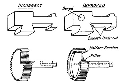
Figure 4: The relationship between design and heat treatment, showing examples of good and poor designs.
Fundamentals of Steel Heat Treatment
Heat treatment of steel involves transforming austenite—a face-centered cubic iron lattice containing carbon atoms in the interstices—into body-centered cubic ferrite with low carbon solubility.
The carbon atoms segregate to form cementite. This process requires mobility or diffusion of carbon atoms, making both time and temperature important factors. Atomic movements occur rapidly at high temperatures but become increasingly sluggish as temperature decreases.
As the cooling rate of austenitized steel increases, the time available for transformation shortens and reactions remain incomplete at 600-700°C. Consequently, residual austenite transforms at lower temperatures with shorter atomic movements, resulting in finer structures. Below approximately 250°C, diffusion becomes so slow that alternative transition structures form.
Rapid cooling affects the critical transformation points in complex ways (Figure 5). Increasing cooling rates produce the following effects:
- Transformation temperatures are depressed
- Ar3 merges with Ar1, producing a single depressed point known as Ar', with formation of fine laminated troostite
- Accelerated cooling causes another arrest to appear at 350-150°C, known as Ar", with formation of troostite and martensite
- Rapid quenching causes Ar' to merge with Ar", resulting in martensite formation
- The arrest associated with bainite formation at 500-250°C typically does not appear in carbon steel but is present in many alloy steels
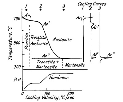
Figure 5: Effect of cooling rate on the transformation of austenite
¡Encuentre al Instante Miles de Diagramas de Tratamiento Térmico!
Total Materia Horizon contiene detalles de tratamiento térmico para cientos de miles de materiales, diagramas de templabilidad, templado de dureza, diagramas TTT y CCT, y mucho más.
Obtenga una cuenta de prueba GRATUITA de Total Materia Horizon y únase a nuestra comunidad que traspasa los 500.000 usuarios provenientes de más de 120 países.