Tensile Testing Of Metallic Materials
Abstract
This article provides a comprehensive overview of tensile testing for metallic materials according to the European EN 10002 standard, focusing on ambient temperature testing procedures. The test methodology involves applying tensile force to a specimen until fracture to determine key mechanical properties. Various technical parameters are defined, including gauge length, elongation metrics, yield strength, tensile strength, and proof strength. The article explains proper test piece preparation, testing procedures, and result reporting requirements, making it an essential reference for materials engineers and quality control professionals conducting standardized tensile evaluations of metals.
Introduction to Tensile Testing Standards
Tensile testing of metallic materials is specified according to European EN 10002 standard. This standard consists of five parts:
- EN 10002-1 - Method of testing at ambient temperature
- EN 10002-2 - Verification of the force measuring system of the tensile testing machine
- EN 10002-3 - Calibration of force proving instruments used for the verification of uniaxial testing machines
- EN 10002-4 - Verification of extensometers used in uniaxial testing
- EN 10002-5 - Method of testing at elevated temperatures
This article describes the terms, definitions, and designations for tensile tests conducted at ambient temperature. The test involves straining a test piece in tension, generally to fracture, for the purpose of determining fundamental mechanical properties of the material.
Key Terminology and Definitions
For the purpose of this European Standard, the following terms and definitions apply:
Gauge length (L) - length of the cylindrical or prismatic portion of the test piece on which elongation is measured. In particular, a distinction is made between:
-
- Original gauge length (Lo) - gauge length before application of force
- Final gauge length (Lu) - gauge length after rupture of the test piece
Parallel length (Lc) - parallel portion of the reduced section of the test piece
Elongation - increase in the original gauge length (Lo) at any moment during the test
Percentage elongation - elongation expressed as a percentage of the original gauge length (Lo)
Percentage permanent elongation - increase in the original gauge length of a test piece after removal of a specified stress, expressed as a percentage of the original gauge length (Lo)
Percentage elongation after fracture (A) - permanent elongation of the gauge length after fracture (Lu - Lo), expressed as a percentage of the original gauge length (Lo). For proportional test pieces, where the original gauge length differs from 5.65√So, the symbol A should be supplemented by an index indicating the coefficient of proportionality used (A11,3 for Lo=11.3√So) or by an index indicating the original gauge length (A80 mm for Lo=80 mm)
Percentage elongation at maximum force - increase in the gauge length of the test piece at maximum force, expressed as a percentage of the original gauge length (Lo)
Extensometer gauge length (Le) - length of the parallel portion of the test piece used for the measurement of extension by means of an extensometer
Extension - increase in the extensometer gauge length (Le) at a given moment of the test
Percentage permanent extension - increase in the extensometer gauge length, after removal from the test piece of a specified stress, expressed as a percentage of the extensometer gauge length (Le)
Percentage yield point extension (Ae) - in discontinuous yielding materials, the extension between the start of yielding and the start of uniform work hardening
Percentage reduction of area (Z) - maximum change in cross-sectional area which has occurred during the test (So - Su) expressed as a percentage of the original cross-sectional area (So)
Maximum force (Fm) - the greatest force which the test piece withstands during the test once the yield point has been passed. For materials without a yield point, it is the maximum value during the test
Stress - force at any moment during the test divided by the original cross-sectional area (So) of the test piece
Tensile strength (Rm) - stress corresponding to the maximum force (Fm)
Yield strength - when the metallic material exhibits a yield phenomenon, stress corresponding to the point reached during the test at which plastic deformation occurs without any increase in the force. A distinction is made between:
- Upper yield strength (ReH) - value of stress at the moment when the first decrease in force is observed
- Lower yield strength (ReL) - lowest value of stress during plastic yielding, ignoring any initial transient effects
Proof strength, non-proportional extension (Rp) - stress at which a non-proportional extension is equal to a specified percentage of the extensometer gauge length (Le). The symbol used is followed by the suffix giving the prescribed percentage, such as Rp0,2
Proof strength, total extension (Rt) - stress at which total extension (elastic extension plus plastic extension) is equal to a specified percentage of the extensometer gauge length (Le). The symbol used is followed by the suffix giving the prescribed percentage, such as Rt0,5
Permanent set strength (Rr) - stress at which, after removal of force, a specified permanent elongation or extension expressed respectively as a percentage of the original gauge length (Lo) or extensometer gauge length (Le) has not been exceeded
Fracture - phenomenon which is deemed to occur when total separation of the test piece occurs or force decreases to become nominally zero
Test Piece Specifications and Preparation
The shape and dimensions of test pieces depend on the shape and dimensions of the metallic product from which they are taken (Figure 1). Their cross-section may be circular, square, rectangular, annular or, in special cases, of some other shape. The test piece is usually obtained by machining a sample from the product, a pressed blank, or casting. However, products of constant cross-section and as-cast test pieces may be tested without being machined.
Table 1. Symbols and designations of the test piece
| Reference (Figure1) | Symbol | Unit | Designation |
| 1. | a | mm | Thickness of a flat test piece or wall thickness of a tube |
| 2. | b | mm | Width of the parallel length of a flat test piece or average width of the longitudinal strip taken from a tube or width of flat wire |
| 3. | d | mm | Diameter of the parallel length of a circular test piece, or diameter of round wire or internal diameter of a tube |
| 4. | D | mm | External diameter of a tube |
| 5. | Lo | mm | Original gauge length |
| - | L`o | mm | Initial gauge length for determination of Ag |
| 6. | Lc | mm | Parallel length |
| - | Le | mm | Extensometer gauge length |
| 7. | Lt | mm | Total length of test piece |
| 8. | Lu | mm | Final gauge length after fracture |
| - | L`u | mm | Final gauge length after fracture for determination of Ag |
| 9. | So | mm2 | Original cross-sectional area of the parallel length |
| 10. | Su | mm2 | Minimum cross-sectional area after fracture |
| - | k | - | Coefficient of proportionality |
| 11. | Z | % | Percentage reduction of area: (So - Su) / So x 100 |
| 12. | - | - | Gripped ends |
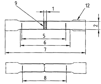
Figure 1: Typical standard test piece
Testing Procedure and Measurement
The test piece shall be held by suitable means such as wedges, screwed grips, parallel jaw faces, shouldered holders, etc. Every effort should be made to ensure that pieces are held in such a way that the tension is applied as axially as possible to minimize bending. This is particularly important when testing brittle materials or when determining proof or yield strength.
For determination of percentage elongation, the two broken test pieces are carefully fitted back together so that their axes lie in a straight line. Elongation after fracture shall be determined to the nearest 0.25 mm with a measuring device with sufficient resolution, and the value of percentage elongation after fracture shall be rounded to the nearest 0.5%.
Table 2. Different types of elongation
| Reference (Figure 2) | Symbol | Unit | Elongation |
| 13. | - | mm | Elongation after fracture: Lu - Lo |
| 14. | A | % | Percentage elongation after fracture: (Lu - Lo) / Lo x 100 |
| 15. | Ae | % | Percentage yield point extension |
| - | Lm | mm | Extension at maximum force |
| 16. | Ag | % | Percentage non-proportional elongation at maximum force (Fm) |
| 17. | Agt | % | Percentage total elongation at maximum force (Fm) |
| 18. | At | % | Percentage total elongation at fracture |
| 19. | - | % | Specified percentage non-proportional extension |
| 20. | - | % | Percentage total extension |
| 21. | - | % | Specified percentage permanent set extension or elongation |
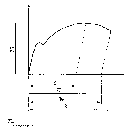
Figure 2: Definitions of elongation
Strength Parameters and Result Interpretation
The designations and related curves for yield, proof, and tensile strength are provided in Table 3 and illustrated in Figure 3.
Table 3. Symbols and designations for different types of strength
| Reference (Figure 3) | Symbol | Unit | Force and strength |
| 22. | Fm | N | Maximum force |
| - | - | - | Yield strength -Proof strength -Tensile strength |
| 23. | ReH | MPa | Upper yield strength |
| 24. | ReL | MPa | Lower yield strength |
| 25. | Rm | MPa | Tensile strength |
| 26. | Rp | MPa | Proof strength, non-proportional extension |
| 27. | Rr | MPa | Permanent set strength |
| 28. | Rt | MPa | Proof strength, total extension |
| - | E | MPa | Modulus of elasticity |
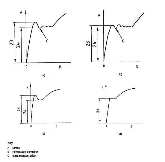
Figure 3: Definitions of upper and lower yield strengths for different types of curves
Test Reporting Requirements
The test report shall contain:
- Reference to the standard
- Identification of the test piece
- Specified material
- Type of the test piece
- Location and direction of sampling test pieces
- Test results
In the absence of sufficient data on all types of metallic materials, it is not possible, at present, to fix values of uncertainty for the different properties measured by tensile testing.